Introducing: The Robopack
A robot that carry's your backpack, so you don't have to!
Portfolio
Robopack Portfolio
Planning & Gantt charts
CAD & Construction of Chassis
Making the drive wheels
Creating a double sided PCB board for motor control
Electronics for the Robopack
Coding & Testing codes for the Robopack
Planning & Gantt charts
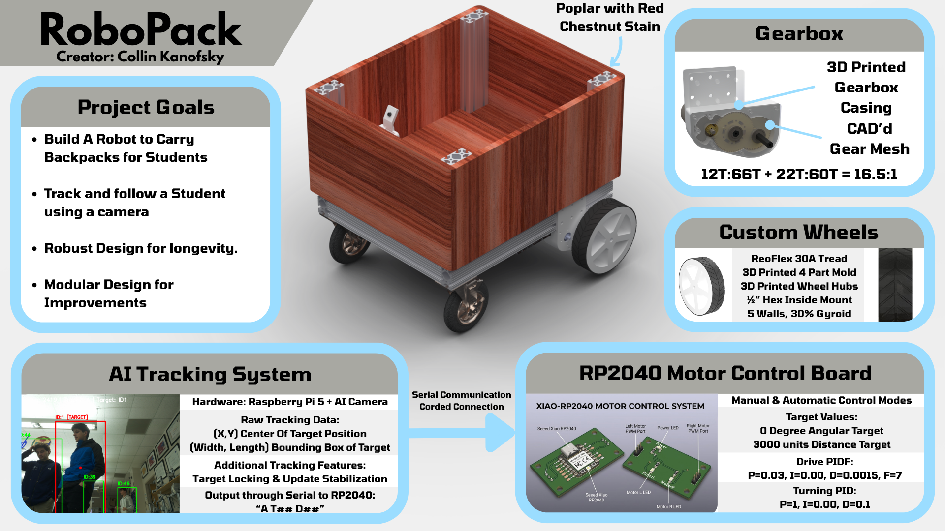
I have been working on the brainstorming and planning for this project for over half a year, and these are the realistic goals I have set for myself in order to consider this porject a success. This project takes inspiration from the recent Starship robots which deliver food around college campuses. The main difference between the two projects though is that the robopack with carry backpacks instead and have a very different control and system layout.
Robopack is a backpack-carrying robot built for my senior engineering capstone. The first milestone is a reliable follower robot that can track a person, carry a load, and move safely on campus-style paths. The long-term goal is to grow from simple tracking to autonomy and smarter navigation.
Key requirements:
Updated Robopack Github Files (links to GITHUB repo) Current Robopack Files (.zip)
PCB Machining
What do you want your project to do?
a backpack carrying robot I have named the “Robopack”. This robot will carry around your backpack for you and will give me a starting point for future more intricate and advanced projects.
Is the project for you or someone else?
For me initially, but potentially adverstisable to the school as autonomous helper units.
If someone else, have you talked to them about design specs?
I have talked a bit to an electrician I know about the electronics of the project
Are you considering a group project? What is your part
Not really, but if someone wanted to join me and add on to the project, I would be open to collaborators.
Will your project be inside or outside?
Mostly outside but a bit of both.
Will your project be portable?
Yes, the robot needs to be somewhat portable
Will your project connect to the Internet?
Yes, it will interact with image vision proccesing and speak to a main base computer
Will your project use Bluetooth?
Probably not but it could if I connect phone integration.
Does your project use a vinyl cutter?
Yes, for branding and warning stickers.
Does your project use a laser cutter?
Yes, for initial gearbox prototypes
Does your project use a 3D printer?
Yes, for the wheels and additional complex 3Dparts
Does your project use a large CNC machine (Shopbot)?
Yes for the expensive wood cutting, but also the small for cutting aluminium for the final gearbox plates
Does your project have intelligence (Arduino, Raspberry Pi, computer)?
Yes, a raspberry pi for computing the vision proccesing and communicating back to a home base computer
What are your project inputs?
Camera, Microphone, Switches like breakers and safeties.
What are your project outputs?
Motors, Speaker
How does your project differ from the project that inspired you?
The project that inspired me was the starships but my project will hold backpacks instead of food and provide a base for many more applications in the future rather than limiting the functionality to one aspect.
When was the inspirational project built?
July 3rd, 2014 was when starships took off.
Do you have a tutorial or instructions for your project?
No, I will be taking on the challenge from scratch.
How current is the tutorial?
Does not exist currently.
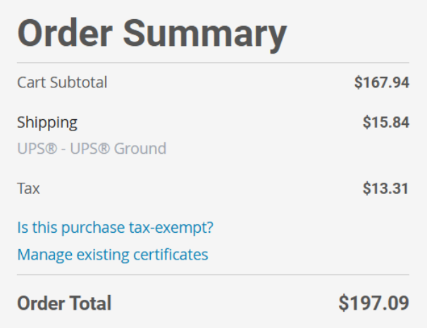
What is the maximum that you want to spend? No more than $75.00
$450, but I will be paying out of pocket as this is a passion project for me.
What are the dimensions of your project?
24”x20”x15” Frame and then some bottom ~6” for the motor + wheels
What materials will you use?
80/20 Framing, CIM Motors, Raspberry Pi, and more that are undetermined as of now.
Have you completed the spreadsheet?
No? I have a rough BOM spreadsheet currently.
Are the parts for your project still available?
Yes, I have a lot of them accesable to me for free or already have them
Are the tools you need for the project found in the FabLab?
Some yes, and some are found in my robotics location.
How will you conceal the electronics?
Using a removable pannel on the bottom of the robot.
CAD & Construction of Chassis
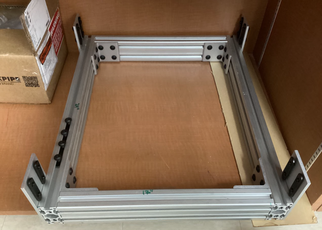
I started off my mechanical planning for the RoboPack by thinking about the frame of the robot. From my previous robotics experience, I have learned that modularity and the ability to re-use and adjust is essential. To ensure optimal flexability, I chose to use 80/20 tubing, specifically the 1530 & 1515 series tubing shown below for robust structure, flexible attachment points, and premade strong brackets that can be re-used and moved.
1530 Tubing 15 Series Bracket
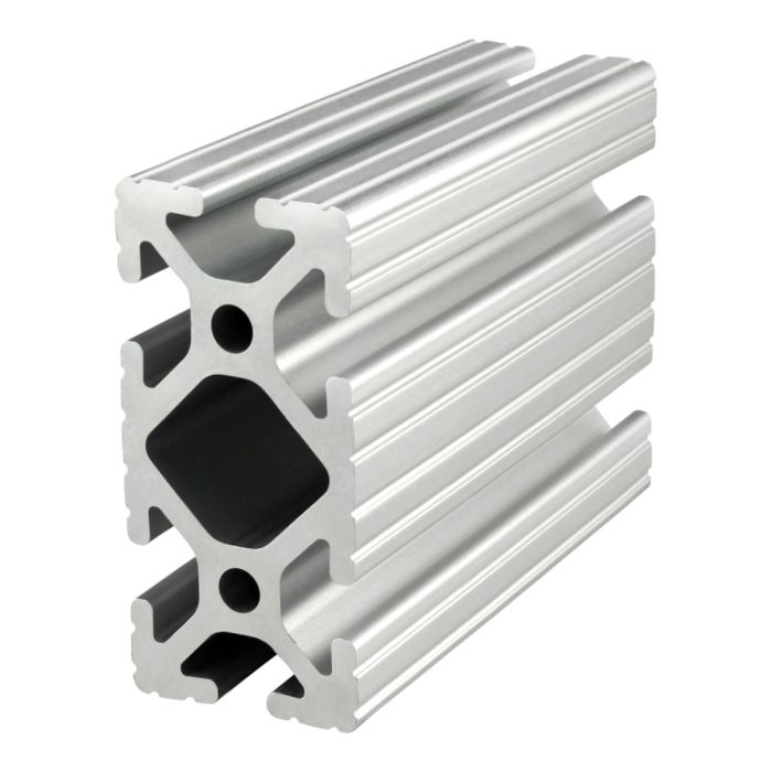
After getting all the functionality down, I plan to use a nice wood to give a natural style to the robot. Another idea I have is to get plastic parts that can cover the machine as well, but that might be more complicated and expensive.
This is a journey through the build proccess describing how the Robopack’s mechanical aspects came to be and the steps taken to get there, Enjoy!
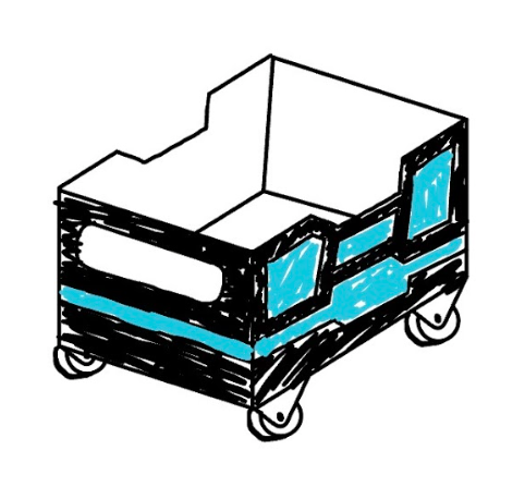
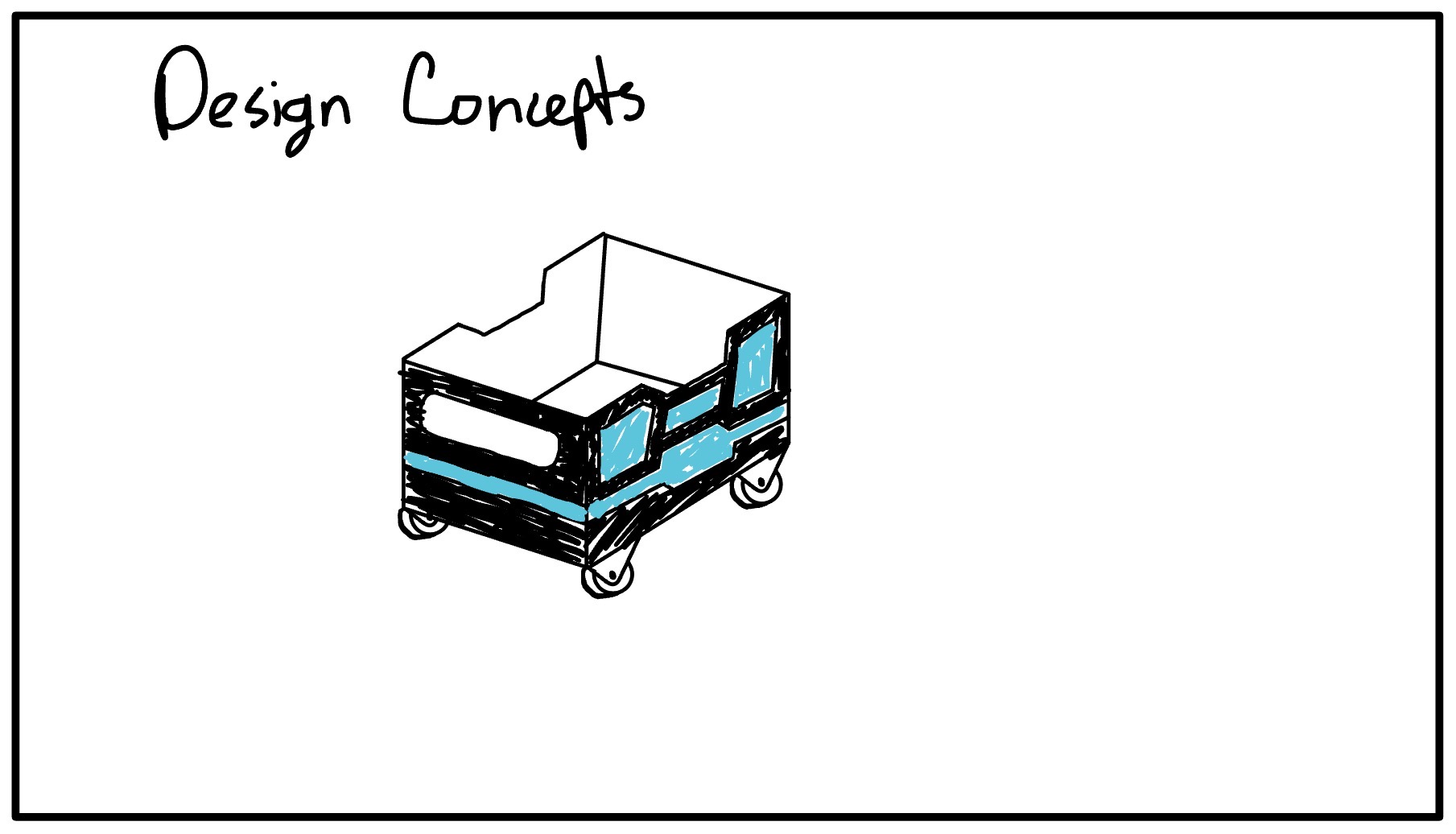
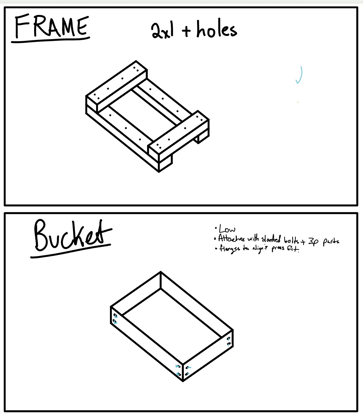
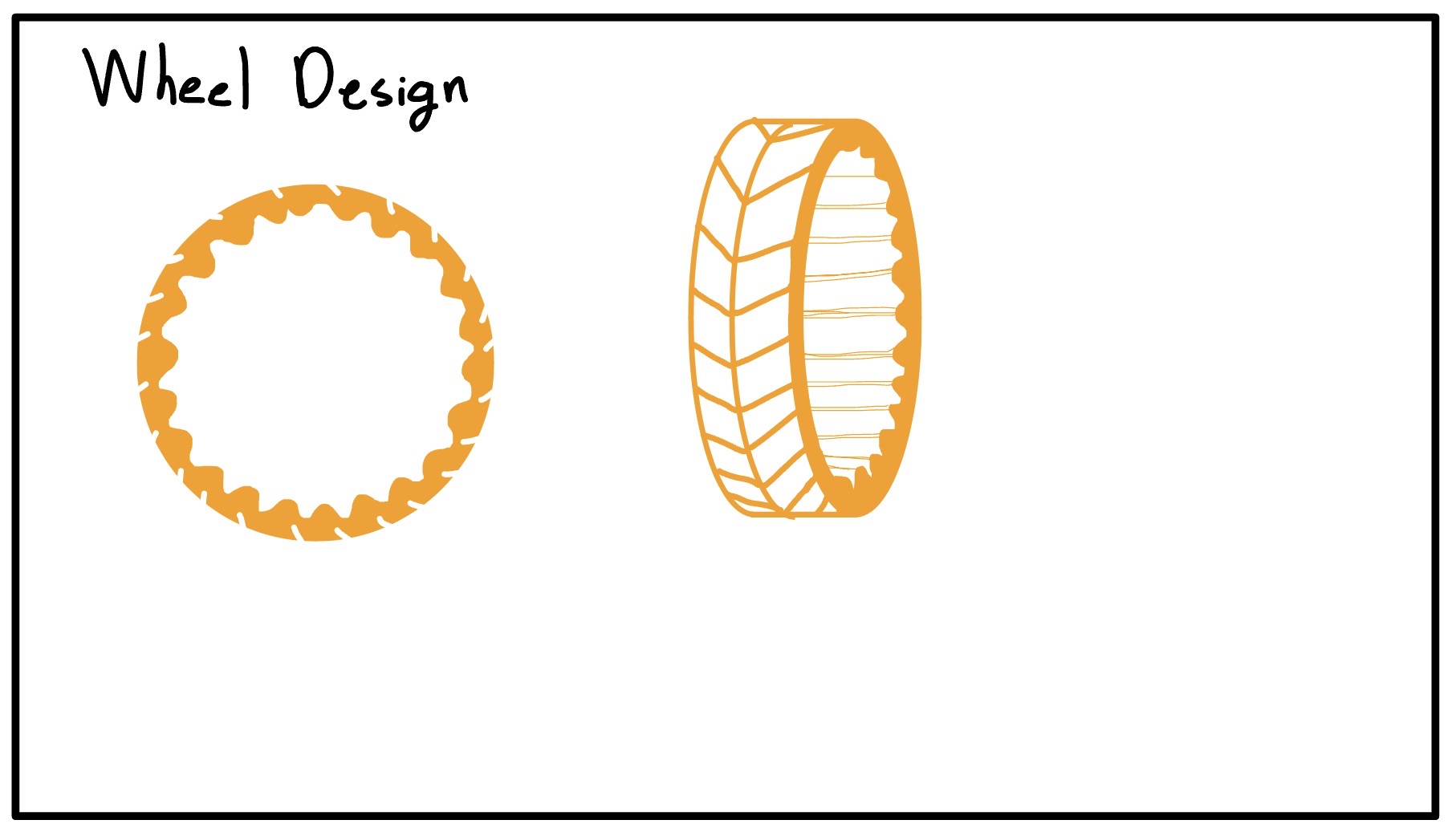
When I first set out to create the Robopack as a junior, I started by sketching out the ideal Robopack which I envisioned. With a stylist, my ipad, and noteability, I set out to draw how the robopack would look, roughly diagram out how the electronics would work, and get a general idea of the features I wanted.
Do Note that this was my first brainstormings and not everything was realistic/stayed the same.
 Note that while the fram was originally going to be made out of 2x4s for cost efficiency, I later chose to use 8020 due to higher rigidity and versatility for future projects.
I used the CAD software Solidworks to design and model the Robopack. The reason I chose Solidworks over softwares like fusion360 or onshape is due to the organization of Solidworks having a seperate assembly vs part studio, being pretty profficient in the software as I do have a proffesion certification in Solidworks(CSWP), and because of the powerfull features solidworks provides such as rendering and more.
Before diving into the CAD, Solidworks is very picky about how and where files are saved and stored, so I started by creating a file system on a github repo to store all my files neatly and easily. The layout is shown below
Github └── Robopack/ ├── DocumentationPhotos ├── Electrical/ │ └── Seeed Control Board Files ├── Mechanical/ │ ├── Asthetic Panels │ ├── Drive Gearbox │ ├── Frame │ ├── FrontWheelBoxes │ └── Main Assembly.sldasm └── Programming/ └── V1RobopackCode/ ├── RaspberryPi Code └── Seeed Code
The first gearbox test worked but was extremely loud. I tried lubrication, then adjusted the motor-to-gear spacing. That helped a lot. The final fix was increasing the spacing correctly in CAD (I initially measured diameter instead of radius), which required a couple reprints but brought noise down to an acceptable level.
Here are the steps and workflow on how I bought, cut, preppared, stained, and finished my wood:
When I was searching for a nice outer shell wood for my robopack, I had to main factors in mind. I wanted a wood that would look nice and presentable, but I also didn’t want to spend an insane amount of money on the wood. After looking through some different woods on Lowes website and talking with Dr. Taylor, one of the engineering teachers who is well versed in woodworking, I decided upon using Poplar Wood. Poplar wood is a lighter hardwood which is easy to work with and has a nice grain pattern. The one downside was that it has a greenish tint but the stain should get rid of that green completely.
At Lowes, I bought 5 boards of 12”x24” .75” thick Poplar and 1 board of 8”x24” .75” thick Poplar. This worked out nicely because my robopacks dimensions are 20”x24”x12”(w,l,h) so I would have less cutting to do. The total price of the wood order was ~$130.
I also proceeded to buy some stains in order to make the wood look darker and nicer. I bought Minwax Pre-Stain and 3 different Minwax stains to try some different colors and choose my favorite. I bought the smallest volumes they had but in the end it turned out to be the perfect amount.
Once I had bought all the wood, I planned out where each piece would go and the size of which I would need to cut it too. Before buying I had done some planning to ensure I bought enough wood, but I double checked and layed out the wood before I started cutting it all. Heres the plan:
Left & Right Sides: 24”x12” (3”x3” gap in bottom corners for the 8020 mounting plate) Front & Back Sides: 21.5”x12” ( 1/4” bevel on one side only on 12” edge to give less boxy asthetic) Bottom Sides: 24”x12” + 24”x8” to fill the 20” space (3”x1.5” gap in outer side corners for 8020 tubing)
I also had to cut an 1/8 off several of the so called 24” pieces because they were actually 24.125”
To make all the general shape cuts such as cutting the 24”x12” to 21.5” for the front and back, or correcting the 24.125” to be 24”, I used the table saw as seen below in the short video:
To cut the gaps in the wood, I chose to use the bandsaw instead because the table saw would leave a circular grove in the wood, whereas the bandsaw cuts veritically so I can cut perpindicular angles. The downside was that the clamp on the bandsaw wasn’t super straight, but I tried my best and got the cuts relatively straight. Below is all the wood after cutting:
Once all the boards were cut and I ensured that they would fit their intended area, I began my long and difficult sanding journey to get the boards ready for staining. According to the instructions on the Minwax stain, I used 220 grit sandpaper on a orbital sander on every face of each piece, yes, even the edge faces and gap faces. It took like 2 hours in total I think.
After using the orbital sander, I started sanding the edges & corners of each piece by hand, ensuring everything was nice and smooth, also a massive pain. I think I spent an hour or so and my hand was hurting a bit by the end, but I’m probably fine.
Finally, I used the router table and a 1/4” Bevel bit to make the roundings on the front and back panels. While they turned out a little bit rough, I used the orbital sander with the 220 grit sandpaper and cleaned up the round making it look nice.
Once all my pieces were sanded, I brought them outside to do the final steps before staining the wood. I started by using a brush to get any big chunks of dust or woodchips off the boards. Then, I used a damp paper towel and wiped down each board to try and get all the sawdust off the boards leaving the board ready for the Pre-Stain coat.
Once the wood had dried from the damp towel, I applied the Minwax Pre-Stain I bought on the wood using a foam brush, and set a 10 minute timer. Once the timer finishes, it will be time to stain.
After the Pre-Stain coat dried for 10 minutes, I applied my Minwax 232 Red Chestnut Stain which I had chosen as the color to stain my wood. I once again used a foam brush(different one than the pre-stain!) to apply a coat of stain on the wood. I tried to not make it too thick but I’m not sure if I did it that well, but I tried lol. After staining, I let the piece dry for a day.
Undone yet :0
Making the drive wheels
How to make and mold 3D printed wheels
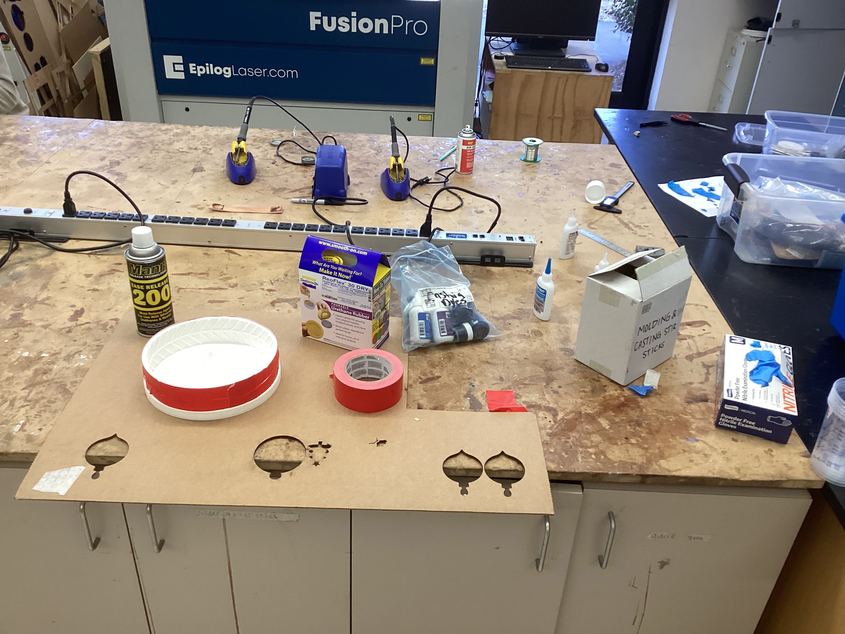
Molding with ReoFlex 30A for wheels
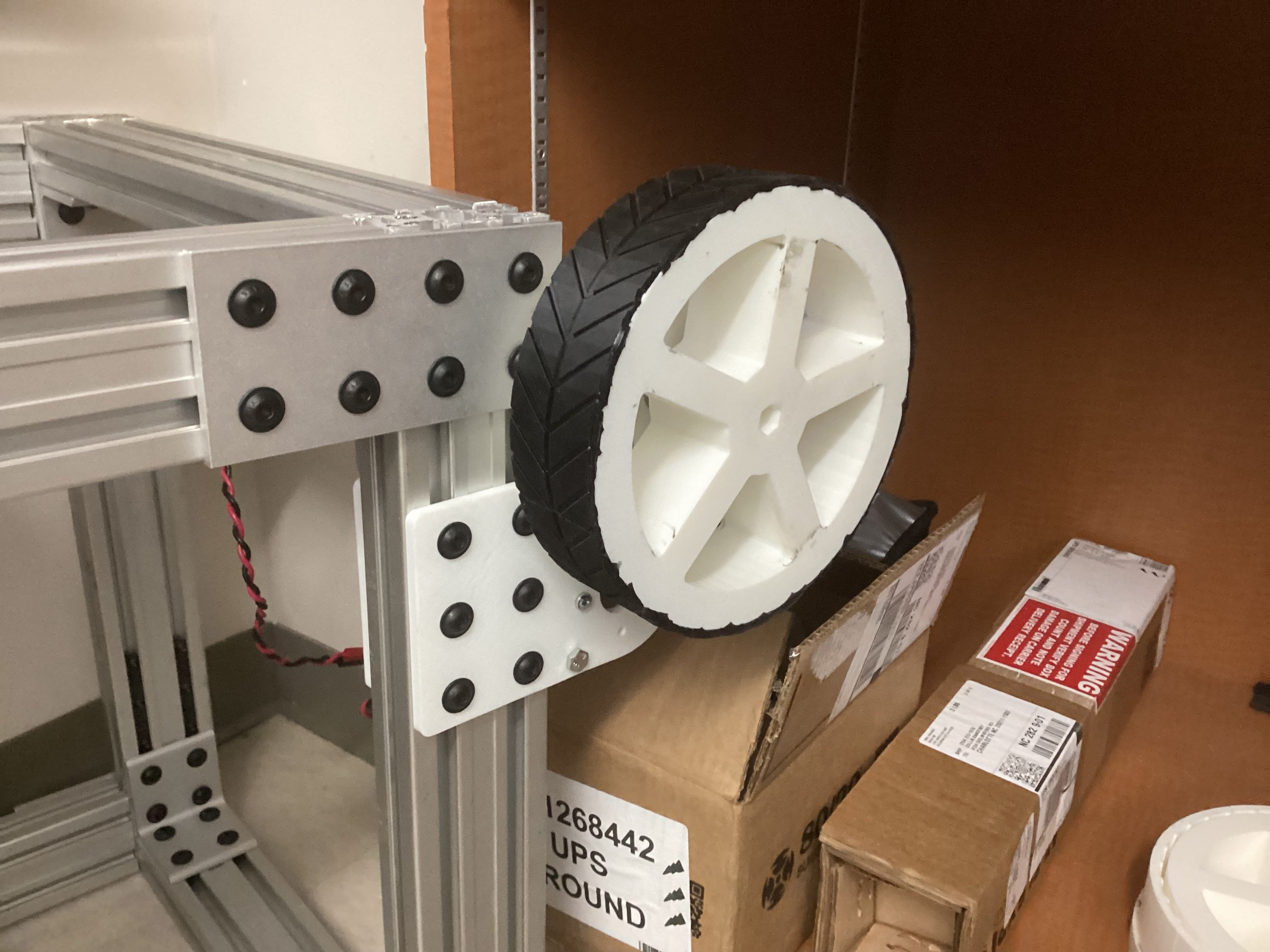
I designed a 4-part 3D printed mold with a hex hub insert so the wheel can mount directly to the drive shaft. The mold is clamped together with a printed top plate and a bottom cover to keep pressure even. For the rubber, I used ReoFlex 30A, mixed 1:1 by volume.
The first pour had a leak between the hub and the bottom plate. I improvised a weighted press using a toolbox to seal it and finished the pour just in time as the rubber thickened.
Demolding took some effort, but the wheel came out clean after trimming the flashing.
I printed a top clamp with a funnel so I could pour faster without overflow. This cut the mold time from ~90 minutes to ~20 minutes.
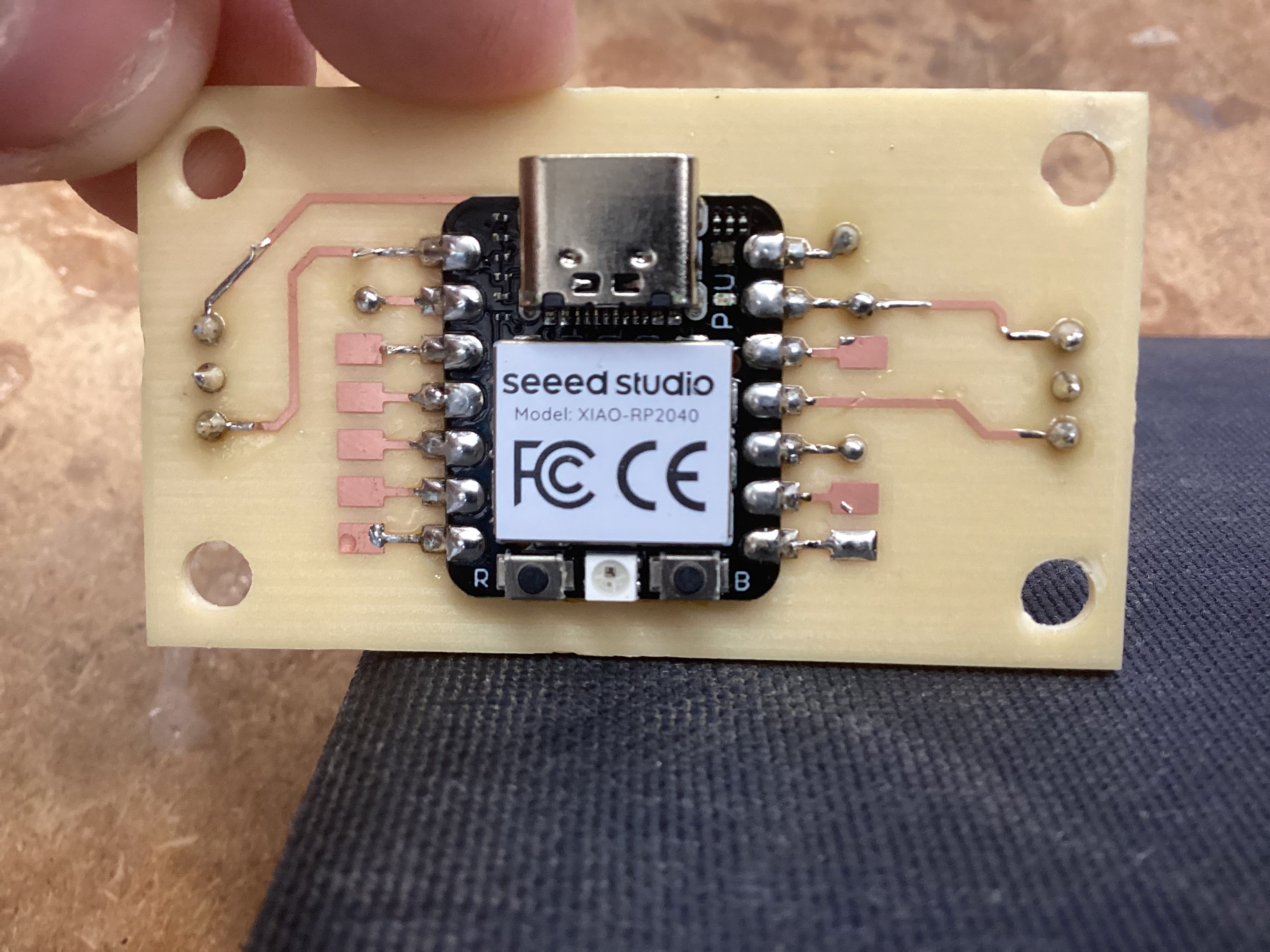
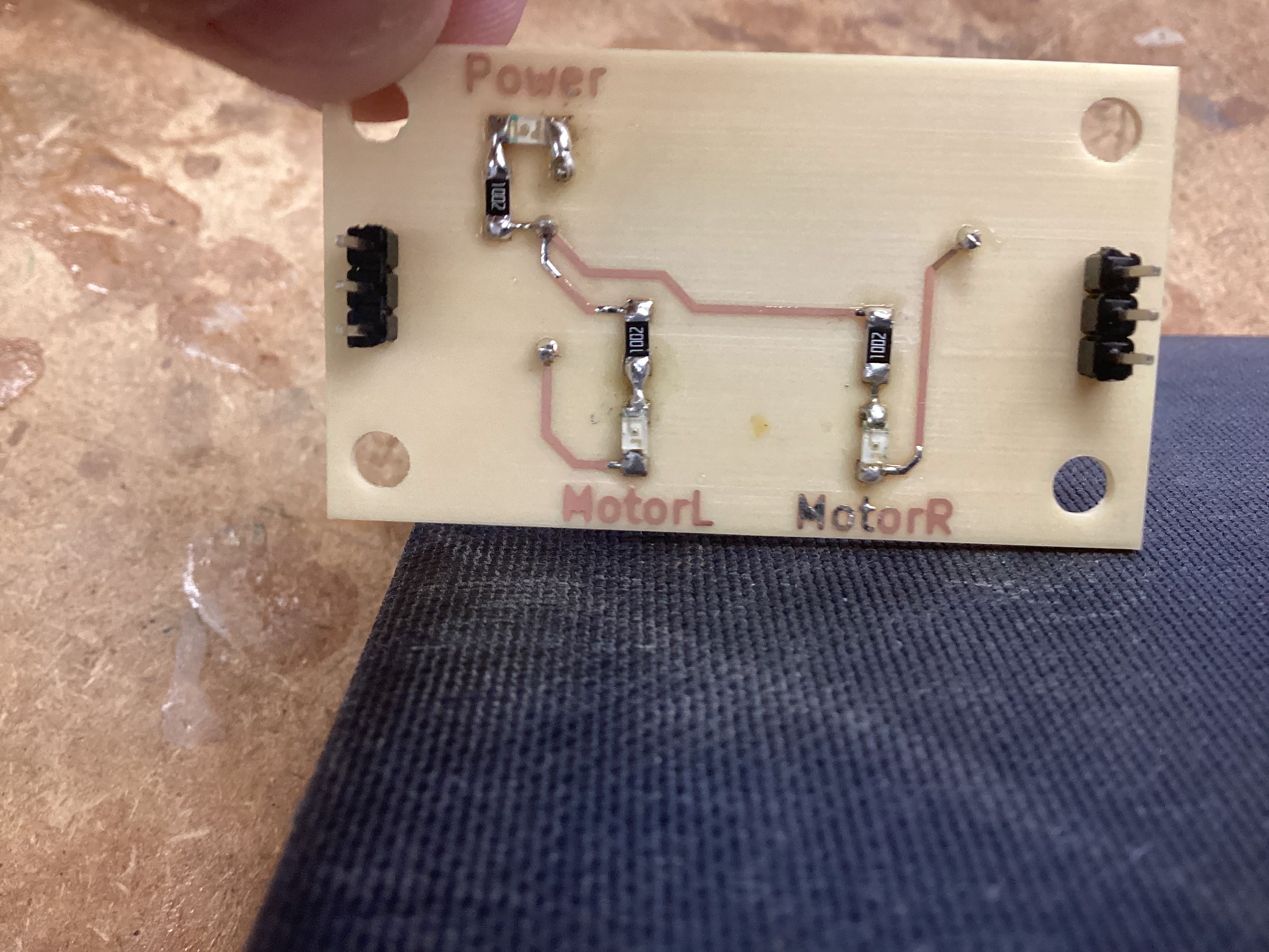
Creating a double sided PCB board for motor control
PCB Board Design Files PCB Board CAM files
I designed and milled a double-sided PCB to mount the Seeed RP2040 and handle motor control connections. This was my first time milling a two-sided board, so alignment and toolpath depth were the main challenges.
Electronics for the Robopack
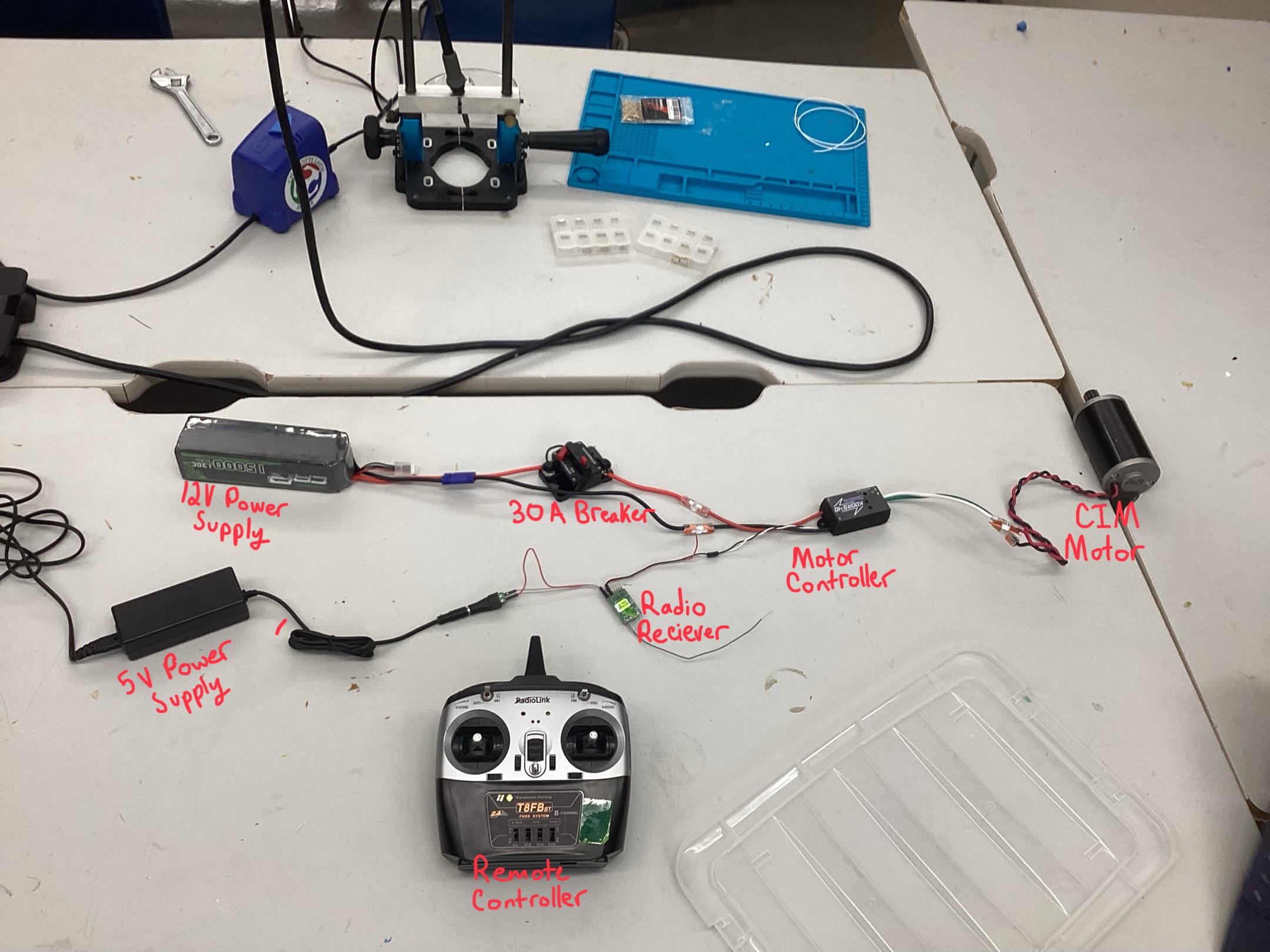
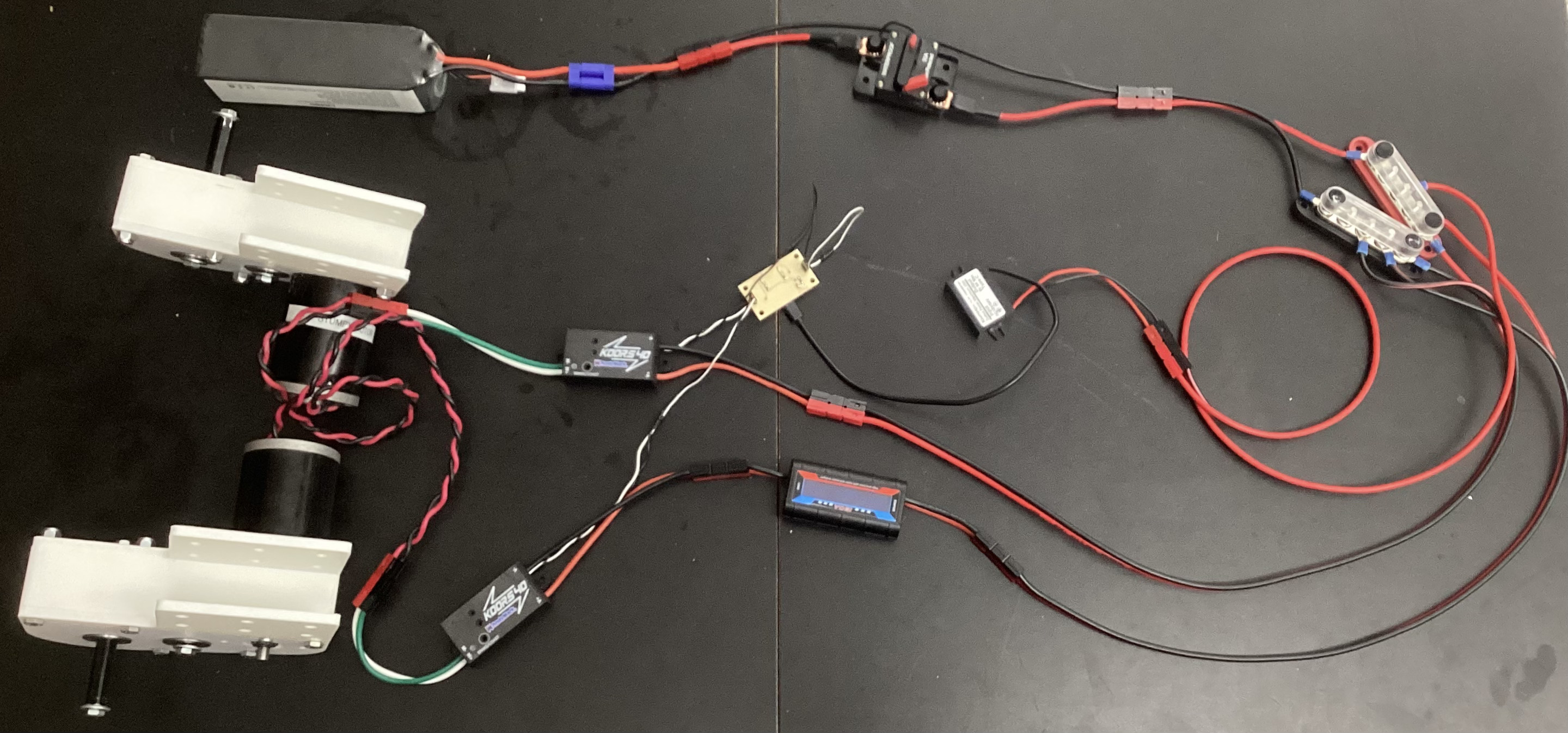
I am planning to use CIM motors which I’ve learned from my robotics teams, the reason for using a CIM motor is due to low costs sitting at around 17$, and the output it produces being 5,330 RPM, with 21.33 in/lbs of torque which is pretty powerfull and should definatly ensure a job well done.
Battery (12V 15000mAh) -> Breaker (30A) -> Motor Controller (Koors40 Brushed DC) -> CIM Motor
RC Controller -> RC Receiver -> Motor Controller PWM
This early test setup helped me validate the motor controller and wiring before the robot frame was complete.
I used Wago lever connectors so I could swap components without re-soldering. For the battery connections, I soldered EC5 connectors onto 12 AWG wire. Later, I ordered Anderson connectors, extra 12 AWG wire, and a power distribution bus for cleaner, safer routing.
I laser cut an acrylic electronics panel and added velcro strips for mounting components. I also designed a 90-degree 3D printed mount for the breaker so it could stand upright. Most components are now mounted, with the Seeed RP2040 kept off to the side for easy programming.
Coding & Testing codes for the Robopack
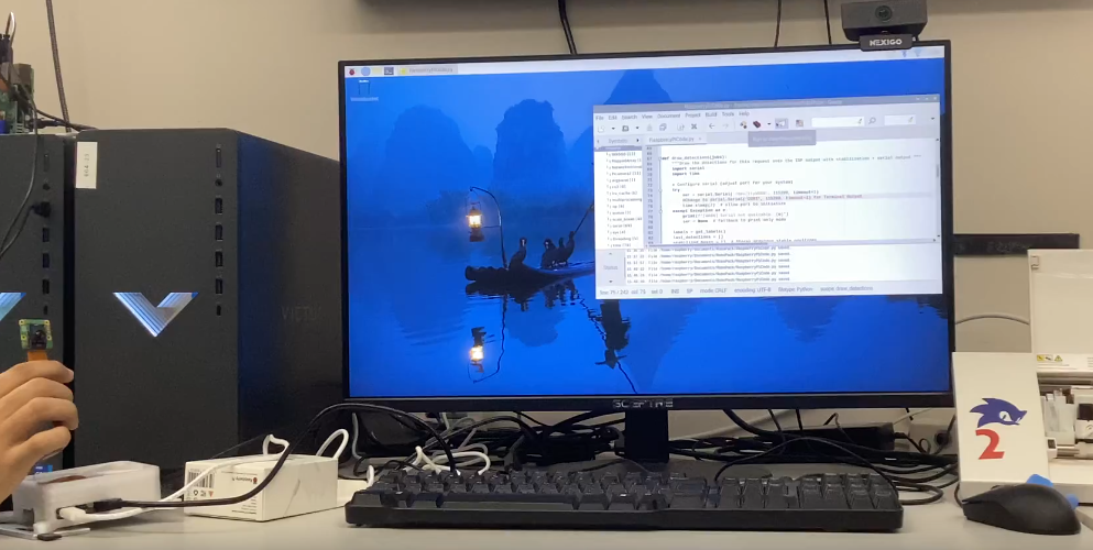
I started with the official rpicam-hello object detection demo and modified it to output bounding box center and size over serial. I added a stabilization filter so small jitter in the bounding box doesn’t cause constant micro-adjustments.
For early hardware tests, I drove the CIM motor using a RC plane receiver sending PWM to the motor controller. This validated motor wiring and safety setup before the full control stack was ready.
I connected the Pi’s tracking output to the Seeed RP2040 so the microcontroller could translate tracking data into motor commands. This gave me the first usable end-to-end pipeline.
The first follow test used a deadzone method: if the target was outside a position/size range, the robot would set fixed motor powers until the target returned to center. This proved the full system worked, but speed and turning were static.
In robotics, we use a method of controlling mechanisms called a PID Controller. The purpose of a PID Controlleris to compare where something is, to where it should be, and correct an appropriate amount to reach the desired destination. This proccess is continuously looped until the the desired destination is reached. Lets break down how the PID works and what PID stands for!
Full credit to RoboFTC for the Following PID Explanantion:
A PID controller is one of the most common control algorithms in robotics. It helps mechanisms reach and hold positions or velocities accurately by adjusting motor power based on feedback.
PIDF stands for:
A PID controller constantly compares a target value (setpoint) to the current value (measured) and calculates how much power to apply.
output = (P * error) + (I * accumulatedError) + (D * errorRate)
1. Calculate Error
error = targetPosition - currentPosition
2. Compute Terms
P = kP * error
I = kI * totalAccumulatedError
D = kD * (error - lastError) / deltaTime
3. Calculate Output
output = P + I + D
4. Apply Output
setPower(output)
For the robopack program I tested today, I chose to only implement a P-Controller to start. The reason for this is due to the margin of error I am allowing which is a lot and the simplicity of a P-Controller. In the future I plan to implement I and D to get more precise motions but currenty am very content with the Robopack following ability. Below is a video of my tuned P-Controller on the robot.
I later moved to a PID control loop for smoother tracking and more proportional motor response. After fixing a sign error in the angle output, I upgraded from P-only to full PID and verified motor directions.
During testing, the robot briefly accelerated toward a person due to a large error spike. Planned safety improvements:
10,000 Changes in area mean significant change 0-600 T value(angle)
Target Values for Mid: T380 D90,000
My name is Collin Kanofsky and I am a senior engineering student at Charlotte Latin School. Throughout my life, I have always loved robots and ended up leading two robotics competition teams where I learned tons of CAD, Leadership, Software, and so many more amazing skills that continute to help me to this day. With this project, the Robopack, I wanted to continue my love for robotics through an impactful and practical means. While I will admit my passion for innovation is what pushes me the most, the possibilities for this project to help others is another big motivator of this project. I hope you enjoy watching my journey and fun as I build this robot!
Timeline

2024 - Junior Year
Super exited about my upcoming senior project, I decided to plan and design the project ahead of time, giving myself a massive head start for the following year.

10/8/2025
Raspberry Pi was Succsesful used to track a person and output their position relative to the center of the screen in the usb serial port.
10/9/2025
After buying the base electronics for moving a CIM motor, the first Succsesful test of controlling the motor happened using a RC controller to ouput the PWM signal, standing in for the future RP2040 Seeed control board.

10/14/2025
This website first pushed through github pages, while there was a preceding older documentation website, the new website exibts a more stylish presentation of my work.
12/9/2025
After constantly itterating the gearbox from not working, to working but way too loud, to quitely working. The gearbox was finaly finished and ready for attachment.
Everyday documentation of robot creation
Makera CAM workflows & documentation
CNC Topo Map Project
Everyday documentation of robot creation
Today, we learned about Git, Github, Github desktop, and the browser github as well. Specifically, we focused on how changes are stored in Git and the ability to create branches of the repo for development without affecting the original branch.
Today, we practiced with Git and created shared Repo’s with each other to practice with collaborator settings on github.
Today, I decided to order the essential electronics for my project, this included the motor controllers, the batteries, and the safety mechanisms.
Today, we did a soldering activity where we practiced surface mount and through hole soldering using a halloween owl kit which lights up when you touch it. The surface mount soldering, internal components, and the finished product are shown in pictures below.
Outside of class today, I used the AI Claude with the Opus4.1 model to generate some starting code for my project. The programs I had made were a RP2040 Seeed program which will control the motors, and a RaspberryPi + AI Camera program which will hand the tracking aspects and math of the camera. I am using the AI formulated code as a launchpad in order to be more efficient and spend more time on customization and troubleshooting, than have to spend that time on writing the base code myself. However, to ensure I understood the code and would be able to edit and modify it, I made sure to go through each line and ensure that I understood why and what the line did, and how modifing that line of code would impact the overall preformance of the program. The initial prompts I inputed are shown below.
write me an arduino code for a RP2040 Seeed which will take input from the usb serial coming off a raspberry pi and move 2 drive motors on my robot using pwm(like how servos are controlled) according to the directions. For input directions, there should be a heading which if is outside the middle range set by me in a variable, then the program should turn until the the heading is once again within acceptable values. Another input will be the distance from the target which also should be kept within acceptable range set by me in a variable. Lastly, have a serial monitor where I can input values for left motor and right motors to test if I want. One last thing is whenever motor powers are set, send back what has been set across the usb serial for the Pi to recieve.
can you now right me a raspberry pi program in pythong prob. that will provide these inputs needed based off a raspberry pi 5 and a raspberry pi AI camera attachment. Also have the raspberry pi host a webserver that allows the user to see the motor power assignements and camera feed. there should be a simple but neat UI for that web page pls.
I have done some thinking and realized that I was going too big on the first code attempt, so I backtracked a bit back to the Raspberry Pi AI Camera Documentation, and completed the instructions as well as ran the example program:
rpicam-hello -t 0s --post-process-file /usr/share/rpi-camera-assets/imx500_mobilenet_ssd.json --viewfinder-width 1920 --viewfinder-height 1080 --framerate 30
This program worked amazing and highlighted me with a bounding box as well as providing a percentage of certanty which seemed to stay above 50% consistantly.
Today, I worked on the electrical for the robot, mainly trying to get power and control to 1 motor for testing. The layout of main power in my electrical testing setup went as such: Battery(12v 15000AmH) –> Breaker(30A) –> MotorController(Koors40 Brushed DC Motor Controller) –> Motor(CIM Motor)
Then, I had to have a seperate control setup which would tell the motor controller how to move the motor. I also had to wire up a 5V power source into the receiver because the PWM output from the motor controller didn’t provide a 5V port, just signal and ground wires. The layout of the control setup went as such: Controller(Wireless RC Plane Controller) –> Reciever(RC Plane Reciever) –> MotorControllerPWM(Koors40 Brushed DC Motor Controller)
I haven’t built this part yet because I chose to focus on the main power layout.
The main focus I had when setting up the hardware was modularity. I want to be able to replace components if I need to, or swap them out wihtout having to unsolder or cut wires, so I decided to use Wago connectors which take to unsoldered raw wire ends, and clamp down a metal plate on the wires forming a connection between the wires on both sides. These connectors worked great, but I sadly only snagged 2 from my robotics team, and I inevitablly ended up needing 4, so I put the final wiring on hold until I could get some more Wago connectors.
I also had to do some soldering to connect the battery to the whole system. I bought some EC5 Connectors off of amazon and soldered them on to 12Ga wire which allowed me to connect the battery to the breaker and the whole system.
Today, I found the github repo for the rpicam-hello program and ran it as a python file which allowed me to make edits to the code itself. I then used the AI ChatGPT from OpenAI to add in code for outputing where the human is in the serial terminal. I chose to use ChatGPT because Claude didn’t seem great at modifing the codes without re-writing everything and that would always end up casuing errors. ChatGPT had me edit one of the functions and everything else stayed the same so when I tested the new code, it worked great and I was able to route the output to my computer terminal temporarily, so I could see the output without another device on the other side of the serial connection.
Here is the original code: rpicam-hello
Here is the updated code which I developed with AI assistance: modified rpicam-hello
This code worked amazing and had very simular functions to the example, but a few key modifications to make it more effective and accurate for my use:
Today, I continued working on the electrical testing setup I started on 10/7/2025. I acquired 4 more Wago connectors from my robotics team and finished up the connections between the motor and the motor controller using them. After finishing the main power setup, I started building the control wiring setup. I used a 5V power supply to power a remote control plane reciever which outputs a pwm signal, used to control the motor. Then I attached the pwm signal and ground to the reciever on the throttle port of the reciever and was able to control the motor using a RC Plane Remote.
Today, I made some orders to make sure my final product would be safer. This order mainly included anderson connectors for modular connections, 12Ga Wire spool, Power Distribution bus that will protect the 12v battery power from contacting anything, but also distribute it to 5 other places.
Over the course of this week, I have moved my website from my boring markdown base template to a Jekyll agency template which is more stylish, cleaner, and has interactive buttons and such to make navigation simpler.
I also ordered some gears from Vex so I can test my gearbox next, now that I can control the motors. Not sure when they will get here but I plan to 3D print the gearbox panels for now and eventually make them out of aluminium with a CNC machine.
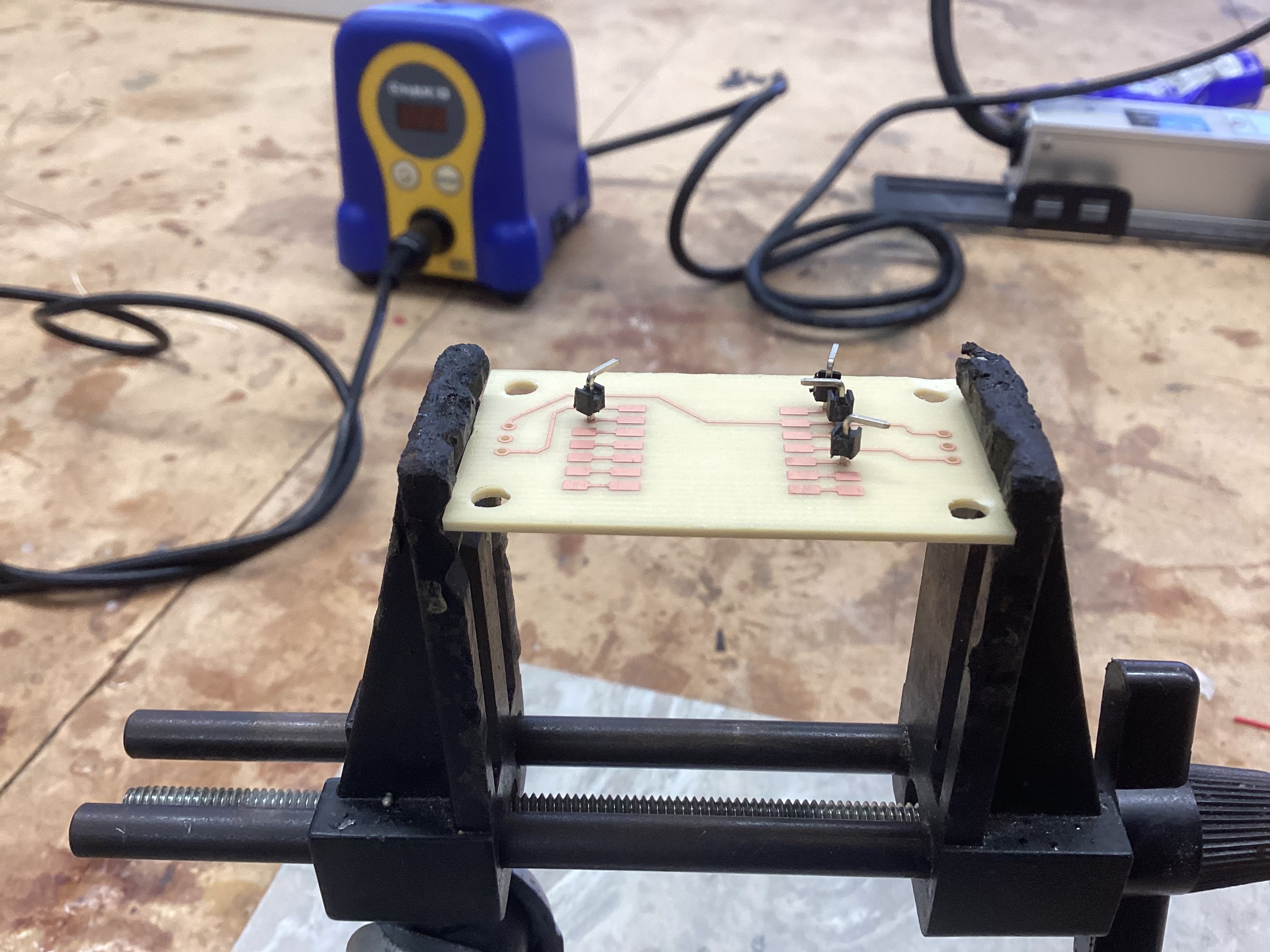
Today, we learned how to use MakeraCAM, a CAM software to take PCB designs and mill them out on Carvera milling machine in our lab. Luckly, I had already designed myself a PCB board for the robopack where the Seeed RP2040 would be, so I decided to take a risk and make my first project my final one.
The main challenge I had to consider with creating my final project board was that the board itself was a two sided board, meaning I would need to do two seperate cut files, but align them perfectly for the PCB to work. I overcame this challenge through making the back a mirror at the same position as the front. What this means is that when I cut, I will cut the front parts first, then flip the board and the back cuts will align with the front hopefully, due to the “mirror line” which is set at the boards width(127mm) divided by 2, which means the two mirrored paths should align.
Today, I finished up my CAM files and cut the board for the robopack. Sadly, I encountered a few issues with cutting double sided boards that I didn’t anticipate:
The biggest issue I ran into was the challenge of getting the board to be in the same position when flipped. If the board is even .1mm off, the holes might not align and the board needs to be remade. This was a challenge I ecountered on my first try, but was able to conquer through focusing the placement and pressure on only the bottom face, which actually revealed that the PCB material was not cut at an exact perpindicular angle.
Another issue I ran into on my first try was that after the front side had cut, when the back side file was auto-leveling, it applied enough force where the material bent and caused a section of the depth on the board to be incorrect. This resulted in a portion of the board missing cut areas due to incorrect height. To fix this, I increased only the back side trace file depth by .05 which in theory, should account for the false reading in leveling, and during my second board attempt, guess what?! it still failed(I was sad). Out of time as well so I shall continue the struggle tommorow. FIGHT ON!!!
File Setup:
Toolpath Creation:
TODAY I FIXED MY WEBSITE!!! This exact page of daily journal documentation is finally visible and working, i have been struggling with getting it all working and with the help of AI and persistence, I finally fixed the formatting and got it all working. Lets goooooo!
Today, I printed the doublesided PCB mount I had designed a bit ago and ordered the bearings for my senior project, I also reviewed what left I had to do before ordering the bulk of the cost, the structure. Below is the list I made:
Pretty chill day for me
PCB Board Design Files PCB Board CAM files
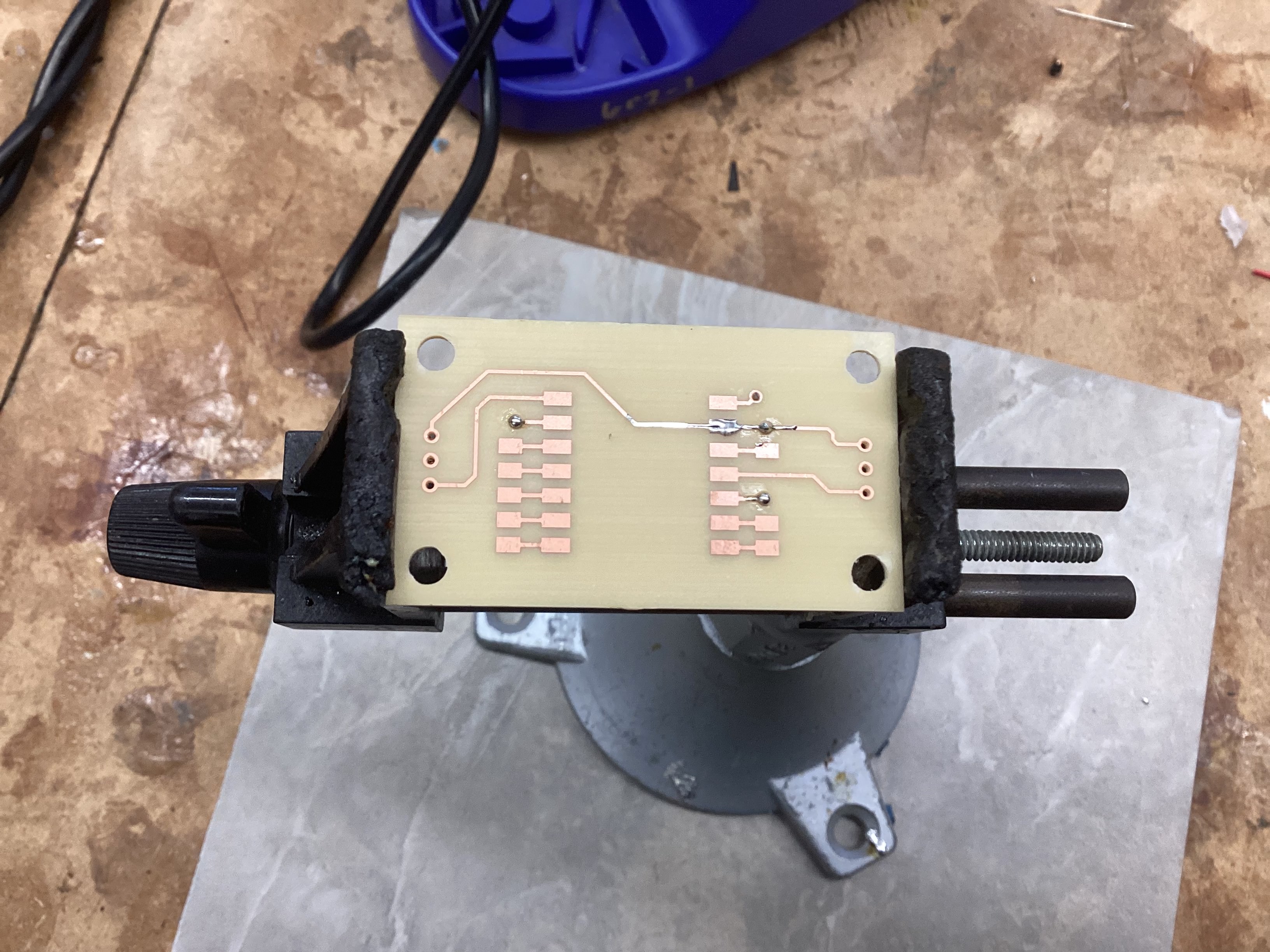
Yay! The board succsesfully cut using the 3D printed Jig I made. By securing both sides of the board, the cut was much more acurate. However, there was still some inacuracy and for some weird reason, a part of the board got hollowed out a bunch. Not sure why but it will still work!
Uh oh… so I might have tried to attach the 2 sides of the board with solder alone… and might have somehow burned the traces off the face of the earth on one side… so today I’m re-milling the board and next time, I am going to use pins in the holes and then trim the ends to connect the sides.
I once again set out to remill my board, and this time, the holes lined up even closer than before. After milling, I used pin headers through the holes, which were a perfect friction fit to keep the pins held in place without holding them, and soldered on the open side where the pin and pad were available. Once soldered, I flipped the borad over and cut off the plastic and extra end parts of the pin header, then soldered those ends onto the board completing the connection. Whle this method had a slight flaw that the circular pads around the hold which weren’t alligned with the holes would have the risk of tearing the hole, I got lucky and while some tracers almost disconnected, all of them remained relatively intact. Below is the board and the step I went through to make the soldering work:
Today I tried to program the seeed board but I think I started to complicated because while the program itself seemed to run great, none of the LED indicators on the board were lighting up to show that power was succsesfully being outputed to the motors.
Today, I focused on obtaining the gears for the drive gearbox of my capstone project. I asked Mr. Dubick to order these through VEX and they came within 3 days of ordering. Once ordered, I then worked on 3D printing the sideplates of my gearbox for testing the gear ratio in the future.
Today, I took the 3D printed side plates for the gearbox and installed 1/2” hex falnged bearings into them to be ready for assembly. Sadly even though the gears arrived, I was unable to assemble the gearbox due to not having the correct hardware and shafts, so I instead made a BOM for what I still needed to get this gearbox up and running.
After my robotics, I used a chop saw to cut 1/2
Today, I finished my Aspire topography toolpaths and updated my documentation to have more info on the CNC milling proccess and update some of the past days which were a bit behind on documentation.
I will admit that I have not been doing day to day documentation recently, but this is because I am trying to make the most of my class time working on my capstone project.
More specifically, I have been working on the gearbox for the Robopack. I bought the hardware I needed and put together my first gearbox test to see if the gearbox worked. Good news and bad news… The good news is that the gearbox works, and that the output looks like it will be the right. The bad news is that the gearbox was really loud, and at full speed it hurt my ears to be near it, so I definetly need to fix this.
The first solution I tried was to lubricate the gearbox, because lubricating the gearbox should quiet the interaction of the gears and make everything run a bit more smoothly. This solution might have had an effect, but it was hard to tell because the gearbox was still really loud.
When lubrication didn’t have the effect I wanted, I started to suspect that maybe the gear spacing was too close, and the extra forced contact was creating the extra noise. After some fidgeting and experimentation where I pushed the CIM motor away from the gearto add a small bit of space between the drive gear and the 1st gear, I noticed a significant decrease in noise. I tested this a few times, and decided to add some slop in the gearbox to relieve the tension between the gears.
This added space between the gears significantly reduced the noise of the gearbox, but sadly when I made the change in CAD, I made the rookie mistake of not double the spacing due to a diamater dimension, not a radius dimension. Therefore, after two reprints and designs, I had finally gotten the noise of my gearbox to a low and acceptable level.
I have also been working on the electical crimping on the side when I have nothing to do but wait for my 3D print to finish. Sadly though, the crimps I bought wouldn’t fit into the connector. I’m not sure if this is a result of buying cheap crimps off of amazon, or if it’s because I didn’t have the correct crimping tool and was just improvising with some pliers and a slightly too small crimper. Either way, I have ordered a new set of crimps that come with a crimping tool. oops though bc I sent it to my sister in georgia… she’s coming home friday so I will get them from her then.
Today, we had a very sad loss…
The reason for which I have dropped 200$ on the harware for my project is because yesterday at robotics, I cut the 80-20 Material for the base of the Robopack, which was the 2 27” pieces and 2 17” pieces. I cut these using a Aluminium Chop Saw, and then used a grinder, debur tool, file, and some helpfull teamates to clean up the edges and make them smooth. Shout out to my robotics mentor Ray Kimble for overseeing the machining proccess and making sure I was cutting safely and correctly!
At school today, I cleaned up the dust and residue from the 80-20 which sat in storage for probably like 10 years with my friend aaron, and then sent the order to 80-20 for the hardware shown at the start.
Due to waiting on the 8020 order & the crimping materials to come in, I will be focusing on the power connection soldering, and the programming in the next coming days.
Quick update from yesterday, I finally cut out my topography file as shown below, I was a bit concerned about the CNC breaking due to the depth of which my file went and the vacuum shoe being in the way, but Dr. Taylor helped me lock the vacuum shoe higher up which made the cut a success.
Today, as I wait for my crimps and the 80-20 materials to come in, I decided to fix the slight issue in the gearbox CAD which made only one of the 4 holes on the motor align, and then started printing a gearbox for both the left and right side so I am ready to attach when the 80-20 hardware arrives. My hope is that when the 80-20 stuff arrives, I can quickly build the main aspects of the robot and have the spacing and layouts to do my electrical wiring. Things are looking good so far!
PARTS ARE HERE!!! my 80-20 hardware arrived and I assembled the main frame of the Robopack shown below. Sadly I have yet to cut the vertical supports which I plan to do Tuesday night.
I also ran into another tragedy. I ordered all the hardware needed for the brackets I bought, but I forgot to order hardware for the gearbox plates. The saving grace is that I releazed that I not only need gearbox hardware, but also hardware for electrical panels, side panels, ect. so I decided that my next mechanical step was to step up and finish the CAD model completely, ensuring I account for all needed hardware in my next order (rip the additional 20$ shipping fee bc I didn’t order these in the 1st delivery).
Today, I worked on organizing my documentation a little bit as well as documenting the topography project. I now show side projects in an appropriate portfolio page instead of being spread within my main daily journal.
I also started the fun task of taking the loads of info within this journal, and putting them in organized sections and formats of the portfolio. So far, I have updated the timeline, the goals, and the hardware section(images fixed in workflow too)
So… I have no idea where the rest of my previous journals went, I might have deleted them by accident but I couldn’t find them. As an update, I have assembled my 8020 frame(not including gearboxs sadly), ran a successful test of both motors using the seeed manual control, and tommorow I plan to order more 8020 hardware for the motor mounting, side panel mounting, and electrical mounting.
Today, I mainly focused on building a Task Manager spreadsheet which keeps track of my tasks, and also helps me manage my time wisely with the Gantt Chart section. One cool feature is that their is a simple tab that only has tasks and their state of completion, and then those states auto update onto the Gantt chart in the second tab for more advanced tracking.
Today I finally laser cut my electrical panel. When I had tried in the past, I kept running into the issue of the logo being a bunch of lines that wouldn’t allow me to fill the inside. To combat this issue, I instead used inkscape to take the dxf and fill the inside because I am more familiar with the inkscape software and then exported a png image of the filled-in logo. This allowed me to bring it into correl draw and trace a logo bitmap of the image, which I then centered with the dxf file of the plate and sent it to the laser cutter.
One slight bump that I hit after laser cutting was that I left the tape sheet on the acrylic to prevent burn marks on the final result. However, I should have only left the tape on the bottom of the acrylic because when the engraving happened, each pixel of the engrave became separated from the main tape sheet, meaning when I pulled off the sheet, the letters were still filled with the tape. To fix this without damaging the acrylic, I used a chisel to scrape the tape out of the letters but it did take me an additional 10 minutes of work.
After the panel was all good and correct, I applied 2 17 inches velcro strips across the top and bottom of the panel for electronics to mount, and added velcro onto all the other electronic components to attach them all together on the panel.
The only components that still need attachment are the breaker, because I want to make it stand straight up, and the seeed RP2040 board because it requires a special case to allow velcro attachment, which I have yet to CAD.
During these days, I finished up the wiring on the Velcro electronics board and made a special 90-degree 3D printed mount to attach my breaker to. I ended up just screwing the breaker into the 3D printed part which worked surprisingly well so I left it at that for now. Below is the final electronics setup minus the Seeed RP2040 board bc I wanted that on the side for programming the aiming algorithm.
During these days, I got the Raspberry Pi and Seeed RP2040 working together and had a decent(I hope) tracking algorithm that seemed to respond to my position in relation to the camera. It was kinda hard to tell how well the algorithm worked without the camera moving on the robot itself, so I decided my next priority would be to make the wheels for the robot.
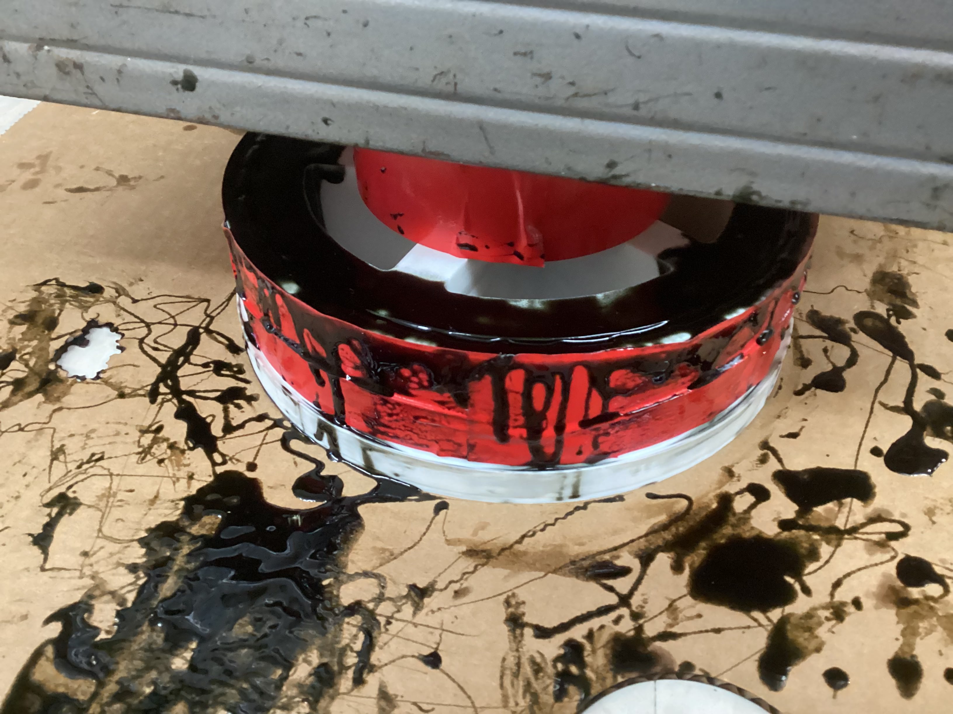
Today I molded the wheel, which was one heck of an experience. I started off with my 4 part 3D printed mold, which then has a center hex peg and a bottom cover/clamp to hold all 4 sections together and under pressure. Then, a 3D printed hex shaft hub was inserted which would eventually be the wheel. To start the molding process, I mixed 100 milliliters of Reoplex 30A part A and 100 milliliters of Reoplex 30A part B, and proceeded to started to pour slowly into the small crack of the wheel mold. I had to poor pretty dang slowly because my opening wasn’t very big and if I poured too fast, the material would start to overflow out of the mold.
As I was pouring in the material, a critical issue appeared. The material was leaking out of the bottom of the mold, at the small gap between the wheel hub and the bottom of the mold. Unsure of what to do, I tried to push down on the wheel hub and pour at the same time, which seemed to stop the leak, but my arm was starting to get tired. Suddenly, I had a genius idea, I asked a friend to grab me the 30lbs toolbox full of wrenches and wratches, a roll of ducktape to give space to pour and built myself a on the fly weight press to stop the leaking mold material. It worked too!
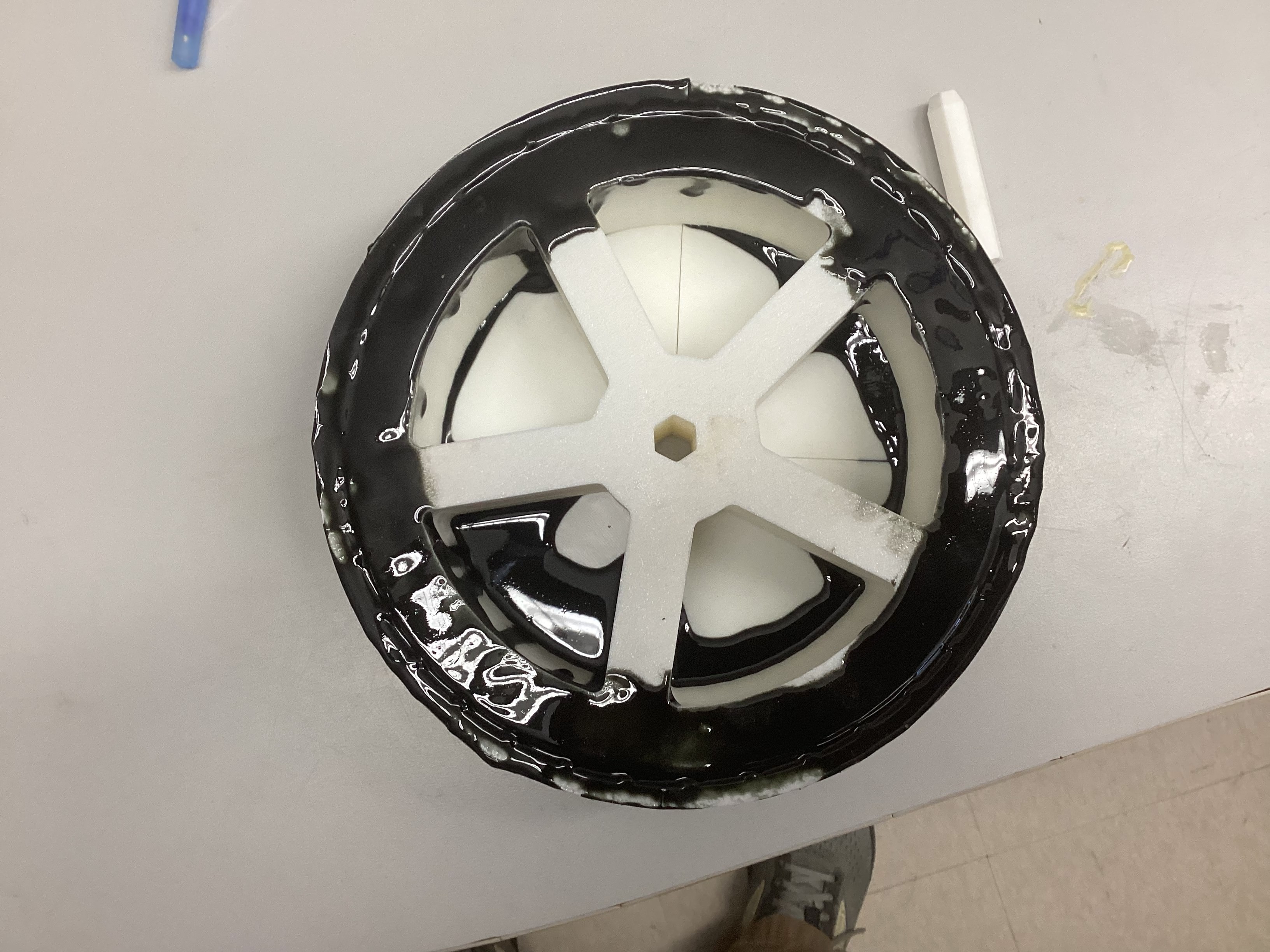
With my issue fixed I proceeded to pour into the mold, with each minute the mold material got less fluid and harder to move, but I was able to fill the mold just in time and put a nice extra coat on top to ensure even if the level of mold went down a bit, the wheel would still have adequate material.
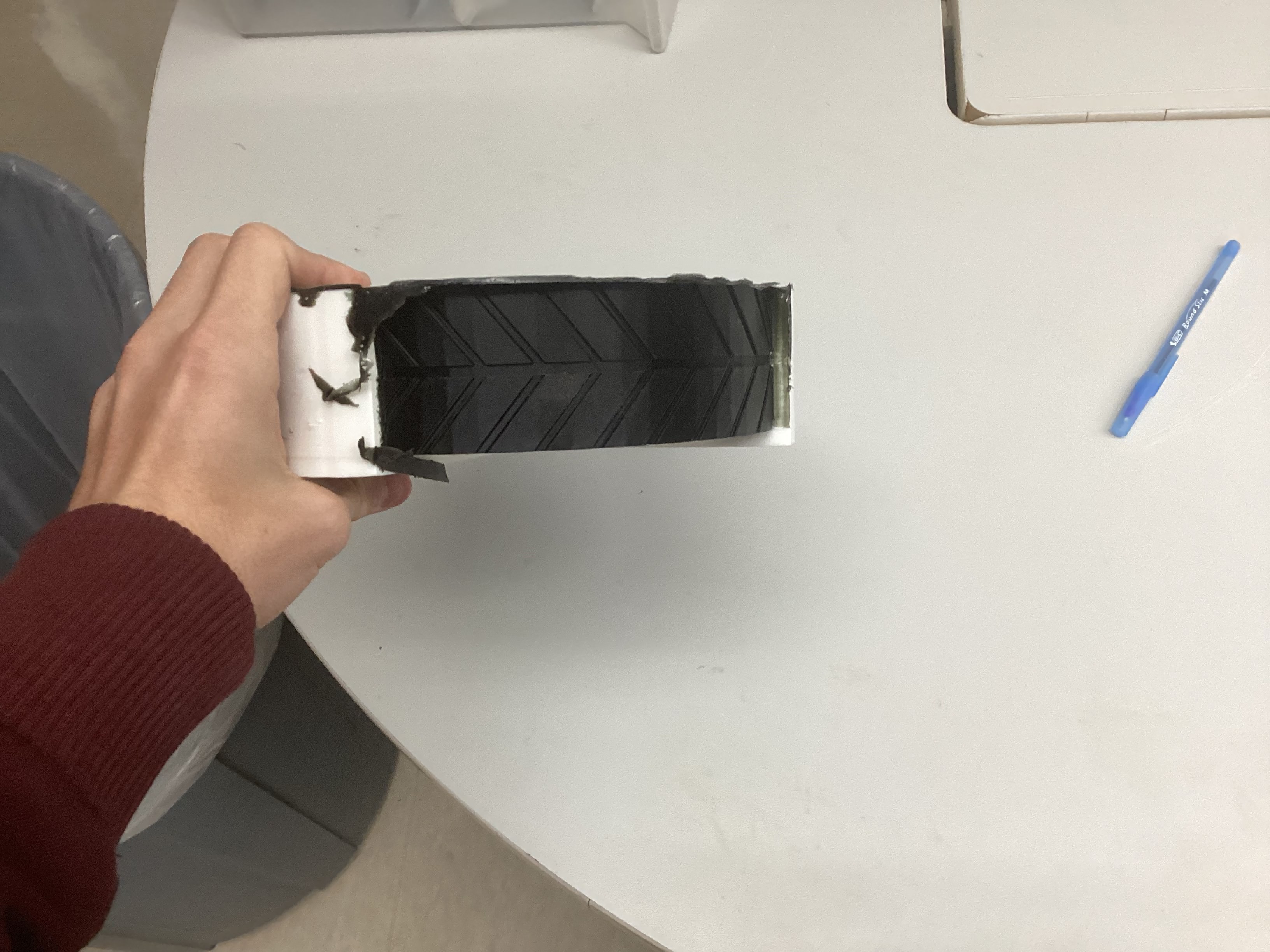
I spent today removing the molded wheel from the mold itself, which was a bit of a struggle, but not terrible. Once I got the wheel out, I used a wire snip and knife to clean up the edges and the wheel turned out great. Based on the result, I decided to use this molded wheel technique for all 4 wheels.
However, before I mold the rest of my wheels, I had a few improvements I wanted to make to the molding process. The first modification I plan to do is hotglue along the bottom of the wheel hub to help solve the leaking issues. Second, I 3D printed a top clamp which also has a funnel so that I have a bigger area to pour into and any extra buildup is contained and funneled back into the mold once the level has decreased.
Today, I molded my second wheel using the new top clamp, which also acts as a funnel, and oh boy, did it make a difference. With the new part, I was able to mold my wheel from mixing to drying in around 20 minutes, compared to the hour and a half I spent on the last wheel. This was largely possible due to the funnel allowing me to dump a large quantity of molding materials on each side and let gravity pull it down into the mold, whereas the old version required me to slowly pour to make sure no overflow occurred.
Today after school, I was able to get the Robopack to follow me!!! I used a rough algorithem on the seeedRP2040 which takes in the output from the vision system on the Raspberry Pi, the output being “A T## D##”. The A stands for automatic, T for translational meaning the angle from center, and D for distance though it is actual area, not distance being outputed(ik I need to fix this later). The seeedRP2040 takes in this data and does a simple deadzone response, where if the values are outside of a chosen range of Distance & Angle, then the robot responds by setting the motor powers to a single response value until the values are back within the deadzone range. For example: If the human is detected to be to the left of the deadzone, the robot will set motor powers to -10% left motor and +10% right motor until the human is in the center again.
While this works great for an initial test and proof of concept, this approach has a few critical flaws. For example: If the human gets further away from the robot, the robot will never speed up beyond its static algorithem which simply says “if human far, go to 10% speed forward” and the same thing happens with turning as well. If you try to mitigate this issue by increasing the max speed, the robot then overshoots its target and shakes back and forth.
Today, I came in with a plan built from my robotics experience. In robotics, we use a method of controlling mechanisms called a PID Controller. The purpose of a PID Controller is to compare where something is, to where it should be, and correct an appropriate amount to reach the desired destination. This proccess is continuously looped until the the desired destination is reached. Lets break down how the PID works and what PID stands for!
Full credit to RoboFTC for the Following PID Explanantion:
A PID controller is one of the most common control algorithms in robotics. It helps mechanisms reach and hold positions or velocities accurately by adjusting motor power based on feedback.
PIDF stands for:
A PID controller constantly compares a target value (setpoint) to the current value (measured) and calculates how much power to apply.
output = (P * error) + (I * accumulatedError) + (D * errorRate)
1. Calculate Error
error = targetPosition - currentPosition
2. Compute Terms
P = kP * error
I = kI * totalAccumulatedError
D = kD * (error - lastError) / deltaTime
3. Calculate Output
output = P + I + D
4. Apply Output
setPower(output)
For the robopack program I tested today, I chose to only implement a P-Controller to start. The reason for this is due to the margin of error I am allowing which is a lot and the simplicity of a P-Controller. In the future I plan to implement I and D to get more precise motions but currenty am very content with the Robopack following ability. Below is a video of my tuned P-Controller on the robot.
Yesterday I spent around 4 hours on a new human tracker that could track one person and ensure that even if a bigger(larger area) target or a different target went in front of the desired target, the program will still track the original person. While I was able to get the raspberry Pi tracking code to work, I was unable to get the Seeed RP2040 code to make the robot follow me. I was super flustered bc I had spent so much time and nothing was working, so I set it to the side and would pick back up tommorow.
Welp, I found the issue today. The Raspberry Pi Tracking code had an absolute value symbol on the heading angle so there were never negative angles outputed, resulting in the robot infinitly spinning.
After I fixed this, I also did a revamp of the RP2040 Code by turning the code into a full PID loop rather than just a P loop, and I also went through and made sure all motor movements and directions were as intended. This took a bit but was definatly worth it in the end.
As I was testing, I ran into a new issue when my teacher Mr. Budzichowski walked in front of the robot and the robot decided that it didn’t like him, so it charged full speed at him…
Ya, bit of a safety issue… luckly he was fast on his feet and was able to skilfully dodge the robot, but I do need a solution for this. A few solutions come to mind. The first is a soft bumper on the outside so that instead of a semi-sharp alluminium frame hitting something or someone, a softer pool noodle impacts instead. Secondly, I want to implement a safety mechanism which shuts off the motor power if a super sudden change in desired power is called for. Lastly, maybe a limit switch on the front of the robot so if an object is hit, then it instantly stops no matter what.
Also I ordered my front wheels but they got delayed to next sunday due to weather…
We have been snowed in for the past 2 days of school, so I have been focused on cleaning up documentation and getting my documentation fully updated. I started by re-organizing the portfolio pages to highlight key parts of the Robopack’s journey, then I used ChatGPT in VSCode for the first time, which allowed the AI to see and change all files in my repo, which was super usefull. I used this tool to change the size of all my images to 1080 width with auto chosen height, which really cleaned up my website. I also had the AI grab documentation from my daily journal and sort the info into each portfolio page which will make my documenting easier because everything I want to referance is consolodated for me.
I also implemented a safety stop into my RP2040 Seeed code where if the change in any one motor is more than a certain threshold, which I set to 30, then the motors are set instantly to stop until the values are within a safe range again. The code is shown below:
if (abs(LP - lastLP) > maxAllowedPowerChange) {
    RP = 90;
    LP = 90;
}
if (abs(RP - lastRP) > maxAllowedPowerChange) {
    RP = 90;
    LP = 90;
}
Today, I focused on getting all the programming testing updated and documented. I had a bunch of videos on my phone from testing and I used today to transfer them to my repo, and shrink the file sizes to be more manageable. As a quick update on progress, I have been told by Mr. Dubick that we have 12 days of class left till the projects are due, but I’m feeling pretty good because all I have left currently is to attach the front castor wheels which come this weekend, test some safety features, make the rasoberry Pi auto boot to my program, buy cut finish and attach the fancy outer wood(poplar wood) to the robopack. Lastly, I want to make a nice reveal video for the Robopack and finish up the portfolio nicely.
For what I got done today, like I said prior I did some documenting, but I also focused on the Raspberry Pi program running on startup, which would allow the robot to run and follow a person simply by turning on the power.
In order to do this, I tried two methods from this tutorial that I found.
The first methods I tried was to run the program using .bashrc. This seemed like a good option due to it
Today I woke up early to go to lowes, bought the nice fancy outer wood, and cut it to the sizes I need. I chose to make a blunt joint at the corner of the wood so that meant for my 24x20 robopack frame, I cut 2x 24” pannels, and two 21.5” pannels which account for the extra wood width on the corners. I plan to use a router to make a .75” bevel on the ends giving a smoother asthetic to the robot. I also cut 4 extra small scrap pieces so that I can experiment with different types of finishes and choose my favorite. I plan to do that tommorow along with drilling the mounting holes into the wood, which I designed a 3D printed template in CAD to help me accuratly drill.
Today I went and cut out indents in my wood to allow the wood to go around the 80-20 brackets. I used the bandsaw and a square to get my cuts accurate.
I also got my front wheels today and attached them to the robopack. I got lucky with the hole placement and was able to simply print some washers and attach 3 of the four holes into the bottom of the robopack securing the wheels.
Lastly, I went and bought some wood stains yesterday to try them out and see if they would make the wood look nicer. I decided to try 3 different stains on my tester pieces and choose my favorite. To explain how staining works, you first have to sand with 220 grit sandpaper, then you apply a coat of pre-stain, and after waiting 15-20 mins, you can paint on a stain into the wood. After staining, you should put on an polyuerthane or polyacrylic finish to protect the wood.
Today, I didn’t have engineering class but during the second half of my free period, I went over and sanded down the cutouts on my wood frame to ensure everything fit where it was supposed to. Next I plan to drill some mounting holes using my 3D printed templates, as well as some wiring holes so that I can eventually move all my electronics to underneath the robopack wood
Today, school was off but the lab was open so I came in to work on the most time consuming part of my project, staining the wood. Here are the steps and workflow on how I bought, cut, preppared, stained, and finished my wood:
When I was searching for a nice outer shell wood for my robopack, I had to main factors in mind. I wanted a wood that would look nice and presentable, but I also didn’t want to spend an insane amount of money on the wood. After looking through some different woods on Lowes website and talking with Dr. Taylor, one of the engineering teachers who is well versed in woodworking, I decided upon using Poplar Wood. Poplar wood is a lighter hardwood which is easy to work with and has a nice grain pattern. The one downside was that it has a greenish tint but the stain should get rid of that green completely.
At Lowes, I bought 5 boards of 12”x24” .75” thick Poplar and 1 board of 8”x24” .75” thick Poplar. This worked out nicely because my robopacks dimensions are 20”x24”x12”(w,l,h) so I would have less cutting to do. The total price of the wood order was ~$130.
I also proceeded to buy some stains in order to make the wood look darker and nicer. I bought Minwax Pre-Stain and 3 different Minwax stains to try some different colors and choose my favorite. I bought the smallest volumes they had but in the end it turned out to be the perfect amount.
Once I had bought all the wood, I planned out where each piece would go and the size of which I would need to cut it too. Before buying I had done some planning to ensure I bought enough wood, but I double checked and layed out the wood before I started cutting it all. Heres the plan:
Left & Right Sides: 24”x12” (3”x3” gap in bottom corners for the 8020 mounting plate) Front & Back Sides: 21.5”x12” ( 1/4” bevel on one side only on 12” edge to give less boxy asthetic) Bottom Sides: 24”x12” + 24”x8” to fill the 20” space (3”x1.5” gap in outer side corners for 8020 tubing)
I also had to cut an 1/8 off several of the so called 24” pieces because they were actually 24.125”
To make all the general shape cuts such as cutting the 24”x12” to 21.5” for the front and back, or correcting the 24.125” to be 24”, I used the table saw as seen below in the short video:
To cut the gaps in the wood, I chose to use the bandsaw instead because the table saw would leave a circular grove in the wood, whereas the bandsaw cuts veritically so I can cut perpindicular angles. The downside was that the clamp on the bandsaw wasn’t super straight, but I tried my best and got the cuts relatively straight. Below is all the wood after cutting:
Then, I used some 3D printed drilling templates I made previously to help me drill consistent holes for mounting the boards. I didn’t have a metal busing in the templates so I had to be carefull to drill through the template, not drill the template itself.
Once all the boards were cut and I ensured that they would fit their intended area, I began my long and difficult sanding journey to get the boards ready for staining. According to the instructions on the Minwax stain, I used 220 grit sandpaper on a orbital sander on every face of each piece, yes, even the edge faces and gap faces. It took like 2 hours in total I think.
After using the orbital sander, I started sanding the edges & corners of each piece by hand, ensuring everything was nice and smooth, also a massive pain. I think I spent an hour or so and my hand was hurting a bit by the end, but I’m probably fine.
Finally, I used the router table and a 1/4” Bevel bit to make the roundings on the front and back panels. While they turned out a little bit rough, I used the orbital sander with the 220 grit sandpaper and cleaned up the round making it look nice.
Once all my pieces were sanded, I brought them outside to do the final steps before staining the wood. I started by using a brush to get any big chunks of dust or woodchips off the boards. Then, I used a damp paper towel and wiped down each board to try and get all the sawdust off the boards leaving the board ready for the Pre-Stain coat.
Once the wood had dried from the damp towel, I applied the Minwax Pre-Stain I bought on the wood using a foam brush, and set a 10 minute timer. Once the timer finishes, it will be time to stain.
After the Pre-Stain coat dried for 10 minutes, I applied my Minwax 232 Red Chestnut Stain which I had chosen as the color to stain my wood. I once again used a foam brush(different one than the pre-stain!) to apply a coat of stain on the wood. I tried to not make it too thick but I’m not sure if I did it that well, but I tried lol. After staining, I let the piece dry for a day.
I then came back the next day and stained the back of the board. However I was unable to do a second coat because I ran out of stain and was just barely able to finish my first coat at the expense of getting stained a bit myself.
Due to time constraints, I did not apply a finish to the wood.
Once the frame was all done, I went to attach my wood boards to the frame, but I ran into a bit of an issue. My bolts were too short to reach through the wood and into the nut below. To fix this issue, I had to buy a 25 pack of 1.125” bolts from McMasterCar because apparently local hardware stores don’t sell this size(I tried…).
Once the screws arrived, I attached the boards to the metal chassis, aligned the top of the boards on the side, and below is how it turned out.
I decided to swap my wiring from the acrylic piece I cut that was a bit too small to fit everything onto the wood. To do so, I used a lot of velcro so everything could be adjustable and nothing truly permanent or needing holes in the wood. I attached most of the electronics on the underside of the robot, but I placed the main breaker and battery on the top so they would be easy to access to turn off the robot and to swap battery’s. I also ended up putting my raspberry pi and camera at the top becasue they are packaged together and by attaching with velcro on the inner front wall, the camera has a good view of the user. Below is my final wiring:
Once the robopack had all the proper electronics attached and the final frame on, I went back into my code to refine the tuning. Originally I tried to tune multiple variables at once, such as tuning Kp and Kd at the same time but I was not getting great results from this and decided to take a step back to think about my approach.
After taking some time to think, I decided to start simple and only use the P of the PID controller to have just direct error based correction. I started with a distance Kp of 0.04 which I had used in previous PID testing trials and a angular Kp of 0.75 which I also once used in previous tests. The first test run was immensely better than any of the other trials I had run before and I knew I was on the right track.
Distance Results:
Angle Results:
Distance Results:
Angle Results:
Distance Results:
Angle Results:
Distance Results:
Angle Results:
To try and hold a more constant following speed, I tried implementing a PIDF controller(tecnically a PDF controller bc I don’t use Integral). The F coefficient called Feedforward is used to apply a constant force to the controllers output, helping the mechanism overcome friction and have more stable movements.
Originally I made the F coefficient myself by simply applying an extra forwards power when the ouput was forwards, and vise versa for backwards. This works really good when it came to the distance and keeping a consistent speed, but when standstill, the power would still apply causing the turning to get messed up and be overly reactive. To fix this, I turned to my best of friends, ChatGPT and asked it about some different solutions I could use. I chose to implement a more complex system which only boosts the power on small inputs for the drive, but any large movements do not have the boost applied. I also tried implementing this on the turning PID but it made it a lot worse, so I only implemented F on the drive portion. Below is the F code concept ChatGPT gave me:
float minMovePower = 7;

if (abs(speedCorrection) > 0) {
  speedCorrection =
    constrain(speedCorrection,
              -speedLim,
              speedLim);

  if (abs(speedCorrection) < minMovePower) {
    speedCorrection = minMovePower * (speedCorrection > 0 ? 1 : -1);
  }
}
The Robopack is working!!! After implementing the PIDF controller for distance, I was happy with the control my robot had and declared the V1 Robopack project a success! I also learned that the Robopack is strong enough to carry me inside it so I had some fun with friends where my Robopack chased them while I sat inside for the ride. Charlotte Latin Fab Lab instagram account posted a video of me in the Robopack and it got 1.4k views or something, which is cool and fun to have my project public.
I have been working on a 1 slide presentation of the RoboPack, I have been using solidworks visualizer to make renderings of differing parts of the project and Canva for the slide itself and the outline.
Today, I worked some more on my 1 slide presentation, I was able to make the solidworks rendering have no background and then orriented the slides background as the rendering, which allowed the shadows and lighting to blend naturally into the slide, instead of having a slight box around the image do to slight change in color bc of the inconsistent color caused by lighting.
The RoboPack slideshow was submited today, and the V1 of the project is officially turned in. During class, a random person was drawn to present their slide and project to the class. Also my Andymark wheels to replace my molded wheels that keep slipping came in today, so I started assembling them, and got the tires and tube on the inner rim. I still need to install the side hub caps and inflate the tube.
Today, we continued watching presentations and I got to present today, which went well. I had the RoboPack folow me on stage, and then presented my slideshow and awnsered questions from Mr. Dubick and my classmates. I also used my free period today to install the side hub caps, and got the tires ready to be inflated.
We back from spring break yall!! It was super fun but do you know what is even more fun! Tuning the Robopack PID’s for an hour!!! Today, I observed the robopacks motion and attempted to make the movements more fluid and accurate. The main change I made today was I implemented a high speed Angular PID to make the robopacks turning less sensitive at higher speeds, and then I had gemini help me with integrating this PID gradually and scale it smoothly as the robopacks speed increased. This worked very well, but it also opened my eyes to the fact that my normal Angular PID might have too high of a D value or the deadzone might be too big causing it to stall before correcting large errors.
I have been optimizing my PID’s during this time and have focused on adding a safety feature to the code. Now, when the camera looses it’s target for more than .2 seconds, the Robopack full stops and waits for the target to be regained until it can move again. While I got the safety feature working fairly easily, It took a long time and many modifications to the code to make sure the safety didn’t negatively effect the previous tracking and kept the following smooth, but I was able to do so by adjusting the incoming data rate and
Today, I continued trying PID tuning and learned about a PID Controller style called a Gain-Scheduled PID, which is simular to what I did with my low speed and high speed PID with interpolation inbetween to smoothly scale the controller between two PID setpoints. I had AI modify the code just a bit to make the Gain-Scheduled PID more defined and easier to read and interperet.
Guess what I did today!? I continued PID testing!! today I focused on getting the highspeed PID to dampen the heading changes at high speeds but was unable to get a satisfactory result. At a low P value, the robopack drove straight and seemed perfect, but would start to veer off to the side and didn’t correct itself. At a high P value, it would way overshoot and literally overshoot so far that the safety kicks in to stop all movement. At a mid level P value, I simply got meh. It would correct but there was still overcorrection. I also tried playing around with the D value but my issue comes down to this. The D is PID only dampens large error corrections, yet for my robopack, I need to dampen the small corrections, while also allowing large error corrections. My ultimate thoughts from today is that I should reduce as many variables as I can from the control, like the usb serial connection, and get data I can graph and interperet to solve. I plan to save what I currently have as a functional version, but create a new code for the raspberry pi which will do both the vision and the commands to the motors, which will reduce latency between the camera input and the PID movements, as well as make graphing the input vs output for PID tuning possible without increasing latency. This will be a pretty big change but I think it has the potential to fix my current issue of high speed straight pathing.
Makera CAM workflows & documentation
For my project, I used a pocket cut between the traces and the edge, and while that makes the end result very clean and have nothing but traces left, it is very time consuming to cut every single part except traces out.
When I thought some more about this situation, I wondered if I could use a contour instead to mill just the area around the traces, and take way less time. However, this concept had an isssues, the 2D Contour Toolpath only creates one path around the traces which might not be enough and additionaly, only one mill bit could be selected, unlike the pocket where a larger and detail bit could both be selected.
One interesting solution to this I thought up was to have 2 contours, the first being a .8mm Corn bit contour which had a .1mm offset, meaning another countour cut with the .2mm detail bit ould take off just the edges achieving good space around each path while also having the nice detailed cut. I have yet to test this theory, but hope to do so.
Before starting the CAM, make sure you have the MakeraCAM application installed, the .grb files for your custom PCB board(should have at least an F-Cu and EdgeCut file).
MakeraCAM is the software we use to take a PCB design file and make toolpaths that the machine can follow to create the PCB.
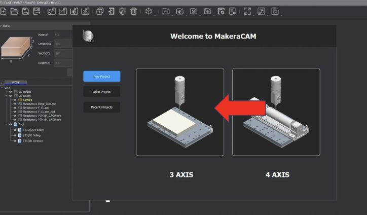
Open up Makera CAM and start a new 3-axis project.
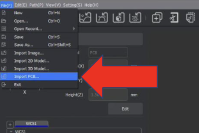
Then we need to import the PCB files. These files are the .grb & .drl files.
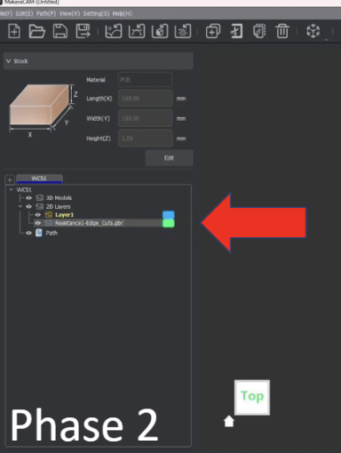
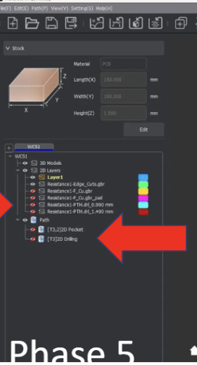
Files will then appear under WCS1
Once all our files are in the software, they will likely not be in the correct position, so we need to move them to have the bottom left of the files 6mm offset in both the x and y axes.
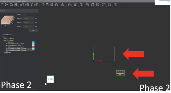
Click and drag over the entire file, which should turn into dotted lines when selected. Then go to the transform tool, or use the keybind “m” to open the move menu. Finally, make sure the bottom left dot in the menu is selected and set both the x and y to 6mm.
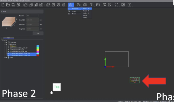
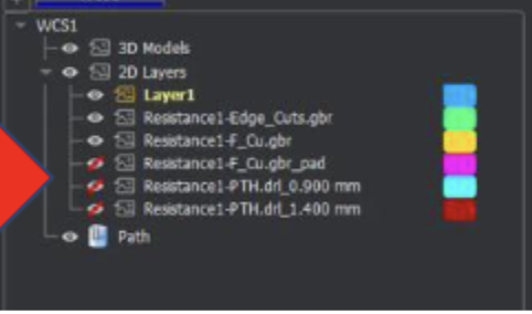
Now that the files are in place, it’s time to start telling the CNC machine how to cut each part, starting with the traces. The key to making toolpaths in MakeraCAM is to effectively manage which layers are hidden to click and drag over only what needs to be selected. For the traces, we want to hide all layers except the following: FileName-F_Cu.grb & FileName-Edge_Cuts.grb . You might notice that there are .grb_pad files, but we will never use these, so keep them hidden so as not to accidentally select them.
When only the 2 main files, F_Cu and Edge_Cuts, are visible, click and drag over the entire area to select everything. Then, zoom in on one of the edges of the Edge_Cut file and deselect the outermost layer of the edge cut. Note that while it looks like a single line zoomed out, it actually is two offset lines.

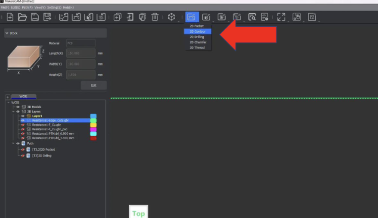
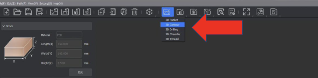
Once the selection is all correct, go up to the top menu and select the 2D paths icon, which looks like an arc with a horizontal tangent line.
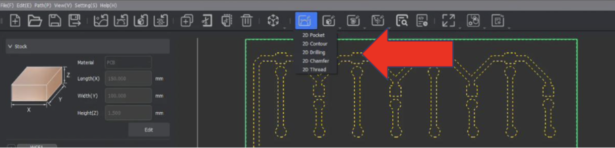
When clicked, a dropdown should appear with a choice for 2D Pocket; select that option. Note that the selection from the previous step should still be active and selected. For the settings, set the End Depth to 0.05mm, Retract to 5mm(for faster cutting).
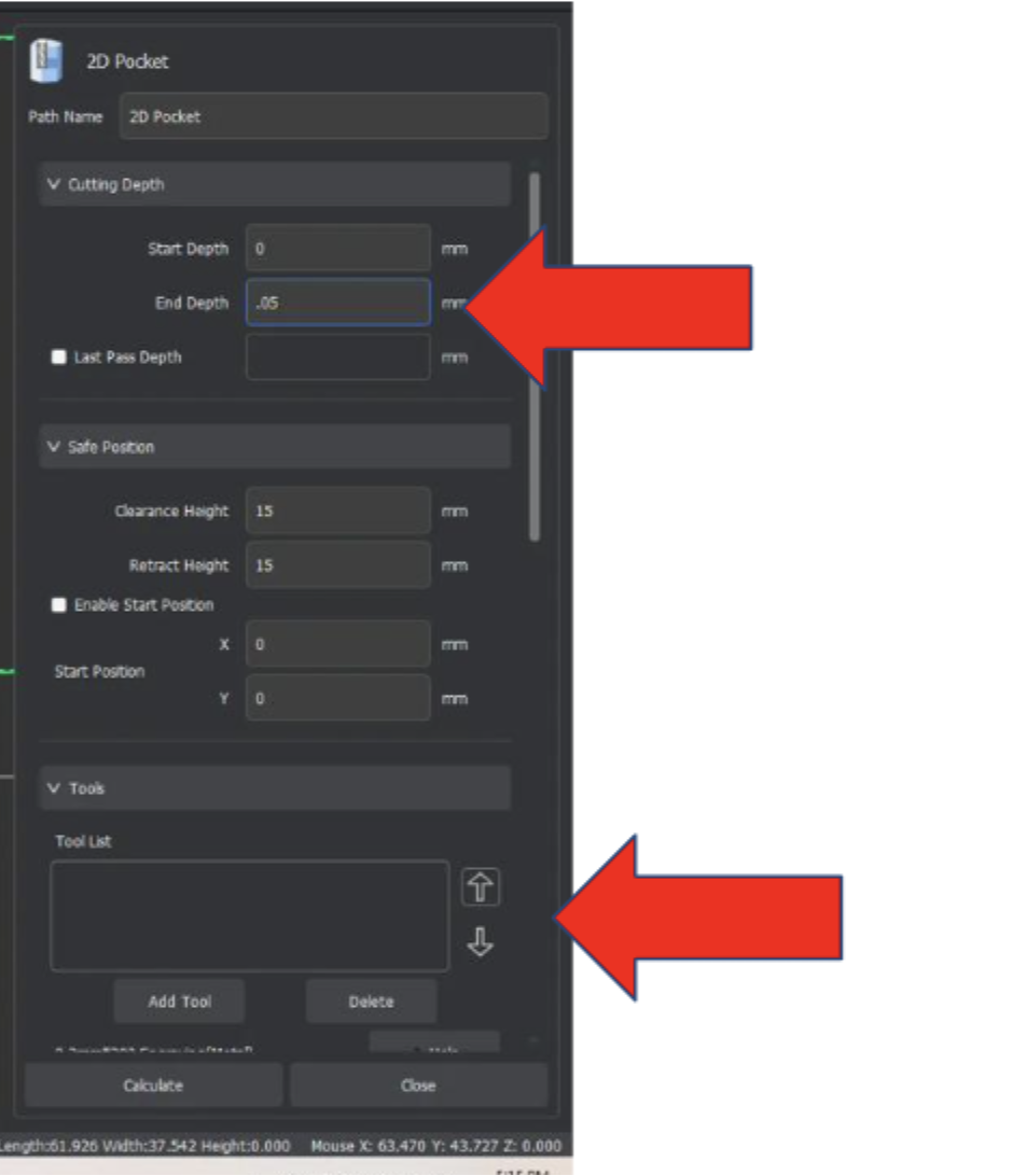
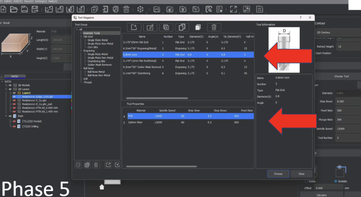
Click on the button “Add Tool” and select the .8mm Corn, click select on the bottom right of that menu.

Do the same for adding the .2mm 30* Engraving Bit(make sure PCB is selected below the Bit Selection menu.).
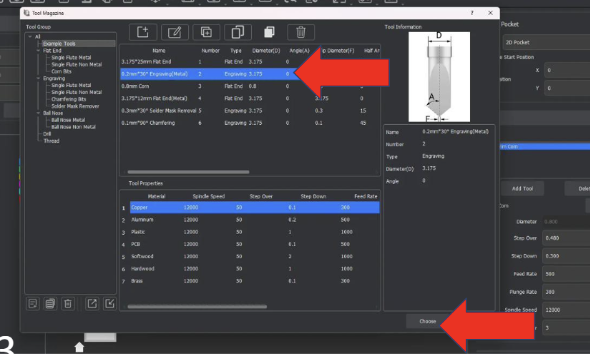
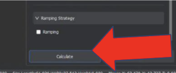
Finally, click calculate at the bottom, and the toolpath should generate. If you would like to hide it until la11ter, it can be hidden using the left menu under the layers area.
Once the PCB traces are cut, we need to add the holes if your design has any. If your file has no .drl files, then skip this step. If it does have .drl files, then we need to go into the 2D path icon dropdown and select 2D drilling.
In the 2D drilling menu, click on the Choose Tool button and select the .8mm Corn mill bit, the same bit we used to cut the traces. Ensure that PCB is still highlighted in the bottom menu of the selection box when the .8mm corn is selected.

Once the tool is selected, set the depth of the drilling to 1.7mm, which is the depth of the PCB board. Then scroll to the bottom of the menu and click calculate.

Once the PCB holes are cut, we can then cut the board out of the big copper sheet by cutting along the Edge cut line. However, unlike with traces where we used a 2D pocket, we will instead use a 2D contour cut to only cut along the edge line of our file. Similarly to the traces, select the inside line of the Edge Cut file.
Once selected, go to the 2D paths icon used before and select 2D Contour.
Once selected, select the .8mm corn mill bit as the tool, and ensure PCB is still highlighted in the bottom menu of the selection box when the .8mm corn is selected.
Once the tool and vectors(edge cut lines) are selected, choose outside as the path of travel to account for the width of the .8mm bit.
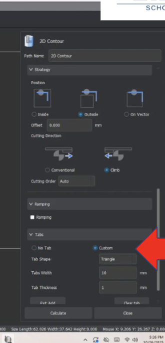
Finally, before we calculate this cut file, we need to make sure that the board won’t come loose mid-cut and potentially fly into the bit. We can do this by using Tabs, essentially small areas of the cut area, which we will skip over to keep the milled PCB board attached to the big copper plate. To add these tabs, scroll to the bottom of the 2D Contour menu and select the circle labeled custom under the Tabs header. Then, click on the button labeled “Add” and select where you want to add Tabs. Typically, you want at least 3 tabs distributed equally on the cut, but this can vary depending on the size and shape of the board.
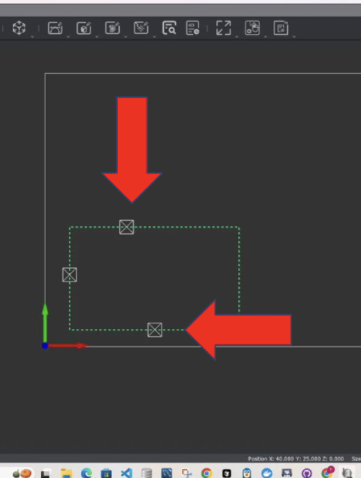
Once the tabs have been added, which is shown by a square with an X in it, you can finally click calculate, and the cut file is complete

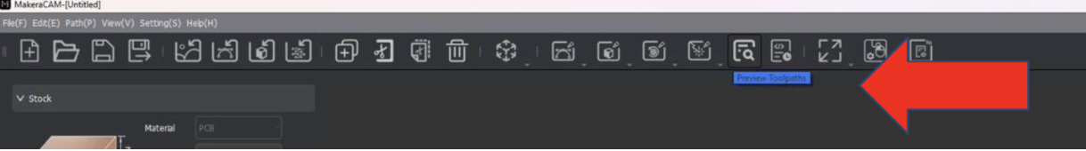
Yay, the board is complete! Now all that is left is to preview and export the toolpaths so that the CNC machine can cut them. To preview the toolpath before cutting, select the preview toolpath icon in the upper menu, which looks like a sheet of paper with a magnifier glass on it.
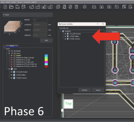
Select this icon and check the boxes for all the toolpaths shown.
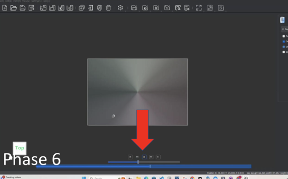
Click the play icon at the bottom to watch the cut preview. The speed of the preview can be adjusted using the slider under the play button, and the upper-right menu box labeled Preview Toolpaths changes what is seen in the preview.
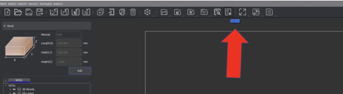
Click exit preview

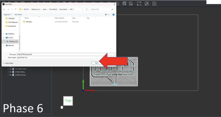
Export the file
Select all toolpaths
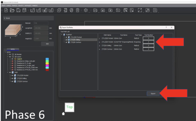
Name file ![LastnameResistorgcode] and save file as a g-code
PCB Board Design Files PCB Board CAM files
CNC Topo Map Project
The goal of this project was to take an area of the world, some geographical feature and CNC the geography on the Carvera CNC machine.
STL Topographical File Aspire crv3d File .cnc Cut File
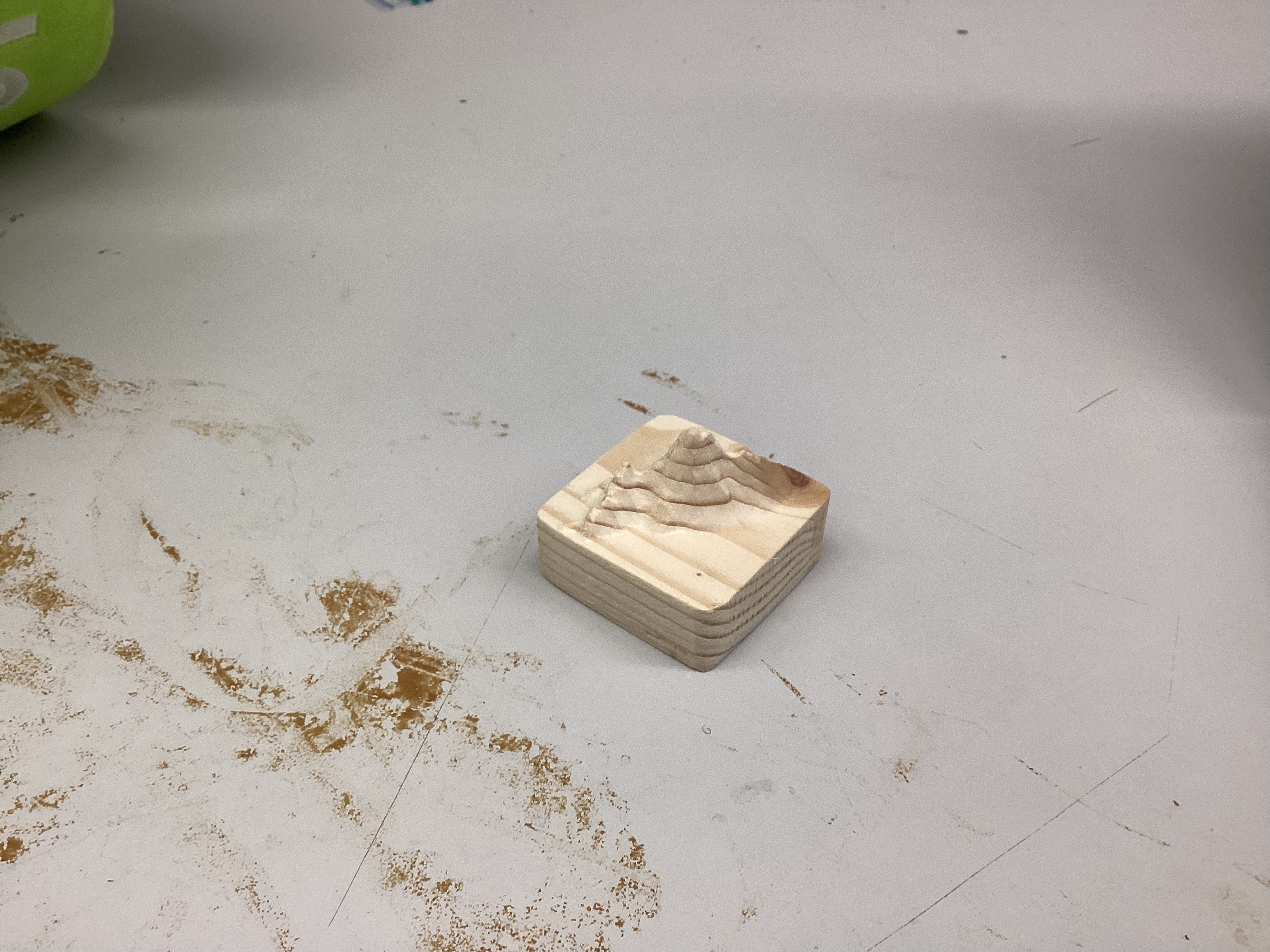
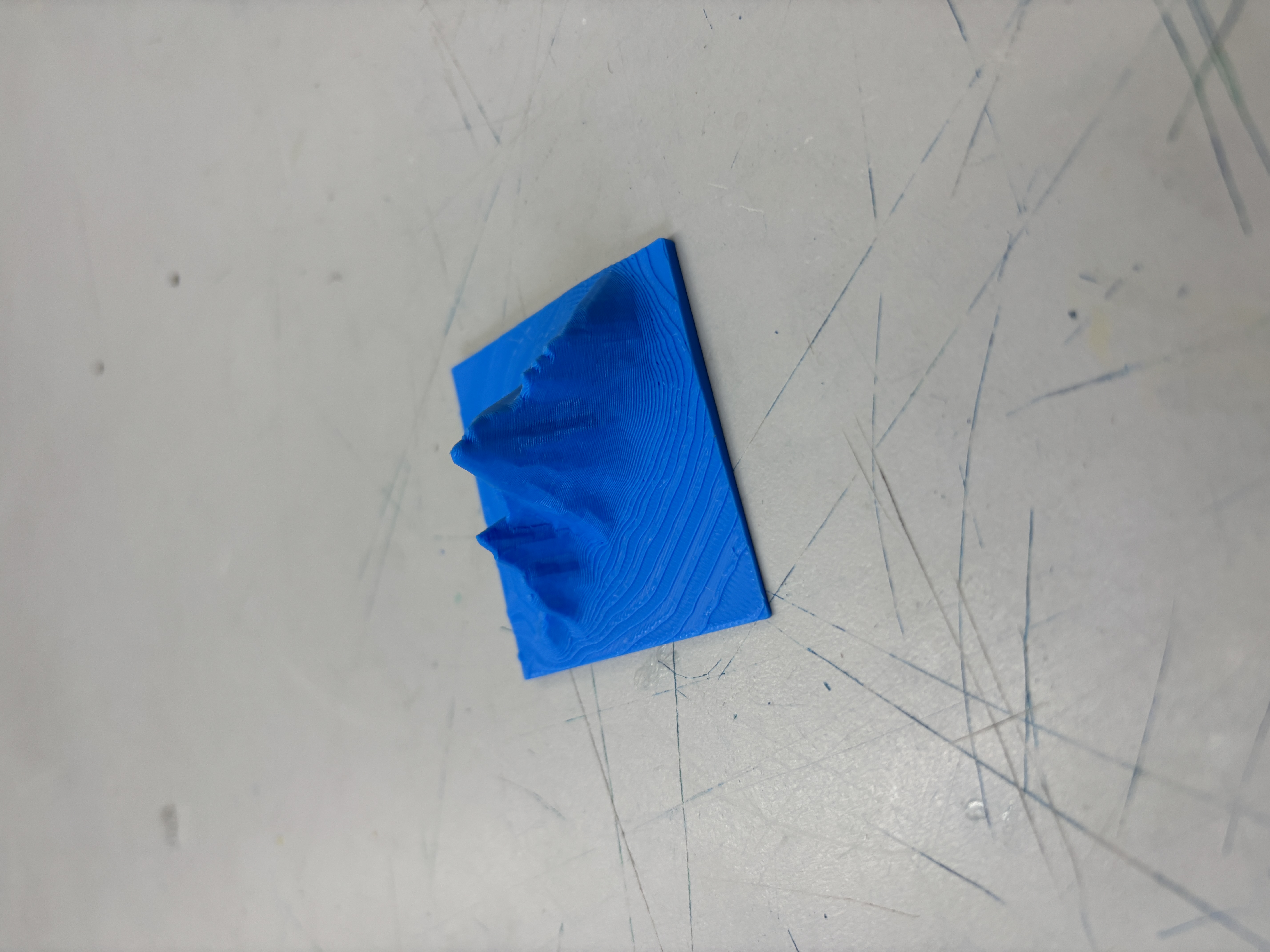
Today I used the software https://jthatch.com/Terrain2STL/ to create a 3D topography map for a quick detour porject teaching 3D depth CNC cutting. For my model, I chose to make the topography of a mountain called Cammleback in Pheonix, Arizona as a birthday gift to my grandma who would always take us hiking there. I 3D printed the model when it was done and looked good.
Today, I worked some more on my Topography Map of Cammleback Mountain, specifically, I learned using an example file how to create and export the toolpaths for this project using the CAM software “Aspire”. At the end of the day, all I had time for was importing the stl and I will make the toolpaths soon. To do the setup, I followed this super helpful workflow by Dr. Taylor.
Today, I finished my Aspire topography toolpaths and updated my documentation to have more info on the CNC milling proccess and update some of the past days which were a bit behind on documentation.
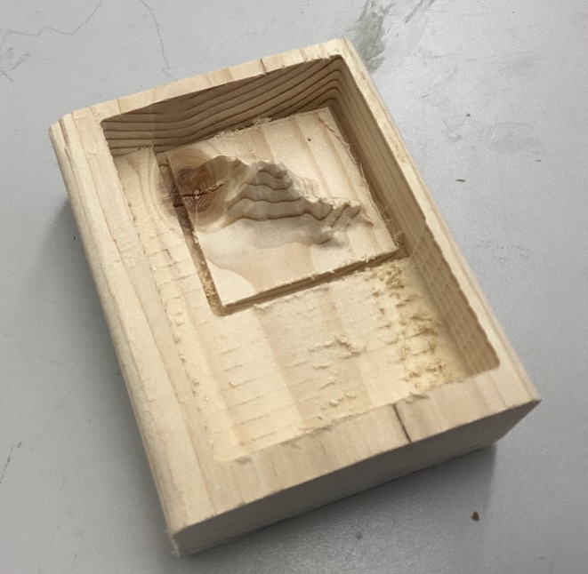
Quick update from yesterday, I finally cut out my topography file as shown below, I was a bit concerened about the CNC breaking due to the depth of which my file went and the vaccumm shoe being in the way, but Dr. Taylor helped me lock the Vaccumm shoe higher up which made the cut a succsess.
This project was really cool because I learned more about the Carvera CNC machines and how to use Aspire in conjunction with Carvera to cut the topo map. I also learned about the importance behind toolpath roughing vs finishing and how one can durrastically reduce time needed by using a roughing pass first and a finishing pass at the end.
One of the main challenges I encountered while completing this project was the Vaccuum broom being too low and having the potential to break due to the g-code. The broom has a spring to go up but nothing in the case of which the brumm metal slide is hit on the side. To fix this, Dr. Taylor bravely risked his life to lift the vaccum brush for me when the machine was paused. We later discovered that the M5 and M3 manual g-code commands would let us stop and start the spindle, which the pause button did not do.
In the future, I want to try using a longer milling bit and make a deeper cut topo because while the mountain looks cool, its width and length are forced to be small because of the depth limit. If I use a longer bit, I would be able to reach deeper and make the base larger making the whole piece more impressive looking.
The Robopack project has been quite the journey, with its ups and downs, challenges and solutions, and ultimately the birth of a working backpack carrying robot. I will admit I had a bit of a head start on this type of project as I have been doing big robotics projects with my robotics teams for 7 years now, but this was still super fun and reminded me of the necessities in order to ensure a large project gets completed.
To begin diving into the process of completing a large project, I had to make sure I had a solid and attainable goal and plan. This meant organizing my list of goals into necessities, attainable, and reach sections to ensure that even if I don’t reach goals due to constraints, I still have a successful project that can be presented and perform as intended. Additionally, to ensure the smooth progression of the project, I created Gantt charts and split large tasks into smaller more manageable tasks that could be achieved in a week rather than a month. This allowed me to feel accomplished at each milestone and lessened the burden of a whole project into small feats. Lastly, one of the key aspects that allowed me to finish my project before the deadline was to not fixate on a finish date, but instead fixate on getting results as soon as possible, and then iterating and improving until time runs out. This mindset allowed me to finish the project early, and spend a lot of time on programming and tuning the movements of the robopack to be smoother, hold constant speeds, and account for friction at low speeds.
While I am super happy with the results of the RoboPack, I have no plans to stop here. To understand what I want to change, we need to understand the current inefficiencies with the RoboPack. The most pressing inefficiency is the turning of the RoboPack is too aggressive when at low speeds, but not aggressive enough at higher speeds, or larger turns. Another inefficiency lies in the lack of safety detection, due to the robots’ only sensor being the AI camera. While there are multiple code level safety’s embedded into the movement code, there are still risks of an object suddenly blocking the frame leading to unpredictable actions. Lastly, the wheels on the RoboPack get dirty easily and don’t have enough friction for the actions the code desires. This is seen through wheel skids when doing large turns or rapid acceleration.
Now that I have identified the inefficiencies within the current system, I can now explain how I plan to mitigate these inefficiencies in the future. For starters, I want to dive more into the PID code of the RoboPack to solve the turning and slip issues. While I do use a PIDF for drive control which accounts for some friction in the wheels, I would like to find a way to have all friction in the robot control accounted for so that both the driving PIDF and the turning PID can be more controlled and accurate. Additionally, I plan to switch from rear wheel drive to front wheel drive, granting better control over turning. When it comes to the lack of safety features, I hope to implement a 360 degree Lidar sensor to get a 2D scan around the robot, and accurately detect any obstacles or dangers while moving. I also see potential for camera and Lidar collaboration for more accurate “distance to human” values. Lastly, I have already begun implementing my solution to my molded wheels skidding and losing traction. I have decided to take a simpler approach to my issue and buy pneumatic wheels which will provide better traction and all-terrain performance, at the cost of a higher price for the wheels.
Overall, even with the inefficiencies of the RoboPack, I am extremely content with the result of the RoboPack project. I can’t wait to continue iterating, improving, and innovating through this project to make the RoboPack so much more. I would also like to give a huge thank you to all the Charlotte Latin Fab Lab teachers and staff, as well as my family and friends who have supported me along the way to make this project a reality. I now feel ready to head off to college confidently, RoboPack in tow.
